E-Mobility & EV Powertrain HV Test
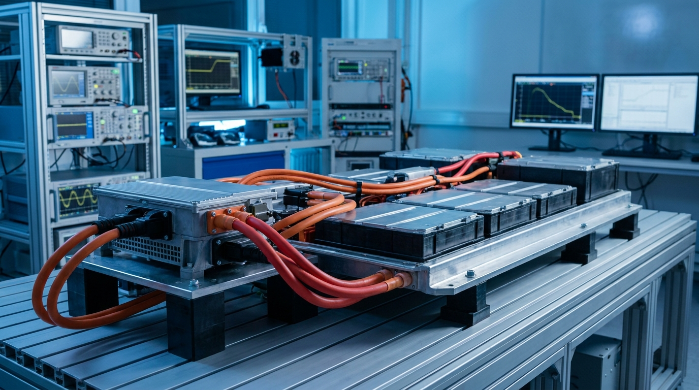
The electrified powertrain runs on a high-voltage bus that did not exist in the combustion era. Traction batteries, inverters, DC-DC converters, on-board chargers, and motors all share a rail that commonly sits between 400 V and 900 V, and the next generation pushes higher. Every one of those components has to be tested for the conditions it sees in service: full bus voltage, the currents that real load draws, and the isolation that keeps that energy away from the chassis and the occupant.
Two demands make this work distinct from ordinary high-voltage test. The first is current. Validating an inverter or charging a battery emulator at 800 V is not a low-current exercise. The supply has to source real power into the load while holding its set point, not sag the moment the device pulls. The second is grounding. Much of EV test is done on floating architectures, where the high-voltage bus is deliberately isolated from earth, and the supply has to match that topology. A hard earth-referenced rail in a potential-free rig either defeats the isolation measurement or trips protection.
On top of that, the work is repetitive and automated. Powertrain and battery test runs across many units, follows scripted sequences, and logs everything. The supply is one node in a larger rig, and it has to take commands and report state without an operator standing over it.
How the BNC PVP-Series line solves it
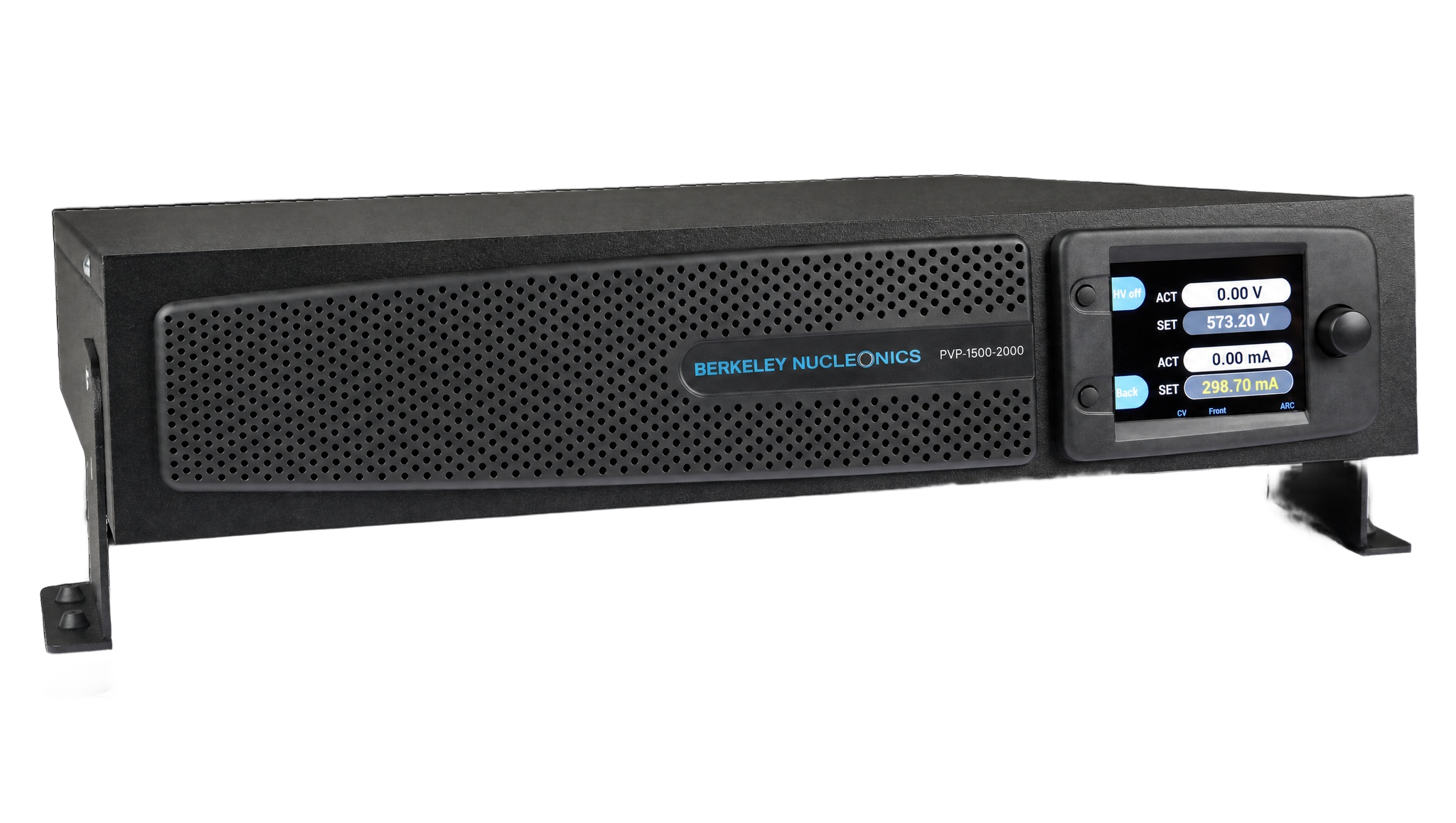
The BNC PVP-Series is built for exactly this combination of voltage, current, and topology. At the 1.5 kV class it delivers up to 2000 mA, which is the headroom a powertrain or battery-emulation rig needs to hold bus voltage while the device under test draws current. The supply is fully digitally regulated, so it keeps that set point under load: load regulation stays at or under 0.05 percent of nominal across a 10 to 90 percent step, and it responds in under 1 millisecond, so a transient on the load does not pull the rail off target.
For potential-free rigs, the PVP-Series offers a true floating output. The floating models present an output that is isolated from earth, so the supply sits inside an isolated high-voltage architecture without forcing a ground reference on it. That is the difference between measuring isolation honestly and fighting the instrument. Where a test plan instead needs a defined earth reference or both polarities, reversible earth-referenced models cover that case.
Because the supply is microcontroller and FPGA based, it talks to the rig natively. Ethernet and RS232 are on board with a standard SCPI command set, the front panel keeps a time-tagged event log, and configurable code protection guards the setup between shifts. Drop it into a benchtop rig or rack it in a 2U slot beside the rest of the powertrain test stack.
Which PVP-Series models and options fit
For e-mobility work the 1.5 kV high-current class is the workhorse, with the floating variant chosen wherever the rig is potential-free.
| Need | Recommended PVP-Series model | Rating |
|---|---|---|
| Potential-free powertrain / battery rig | PVP-1500-2000 flo | 1.5 kV, 2000 mA, floating |
| Lower-power floating setups | PVP-1500-1400 flo | 1.5 kV, 1400 mA, floating |
| Earth-referenced / dual-polarity bench | PVP-1500-2000 | 1.5 kV, 2000 mA, reversible |
| Component isolation above 1.5 kV | PVP-5000-600 | 5 kV, 600 mA, reversible |
Two options matter here. Ramp Control brings the bus up at a defined gradient rather than a hard step, which is safer for energized battery and inverter setups and gives a repeatable rise across every unit in a production validation run. Arc Detection watches for flashover across isolation barriers and can shut the output off when it sees one, which protects an expensive battery emulator or inverter and flags the exact point where insulation gave way. For isolation and dielectric withstand checks on individual components rated above 1.5 kV, step up to the 5 kV class while keeping the same option set.
Recommended configuration
For a powertrain or battery-emulation rig built on a floating high-voltage architecture, the PVP-1500-2000 flo is the right anchor. It supplies the full 1.5 kV bus with 2000 mA of current and presents a potential-free output that sits cleanly inside the isolated topology. Add Ramp Control for a defined, repeatable bus rise and Arc Detection with output shut-off to protect the device under test. Drive it over Ethernet with SCPI and fold it into the rig sequencer.
If the same cell also performs isolation or withstand checks on discrete components, add a PVP-5000-600 in the reversible configuration so the bench covers both the bus-level work at 1.5 kV and the higher-voltage component checks. Rack both 2U units together and run them from the same automation layer.
Talk to an application engineer
Berkeley Nucleonics can help you match a PVP-Series model and option set to your e-mobility test rig. Call 800-234-7858 or email info@berkeleynucleonics.com.
For a quick question, chat with an engineer at berkeleynucleonics.com.