1Product Overview
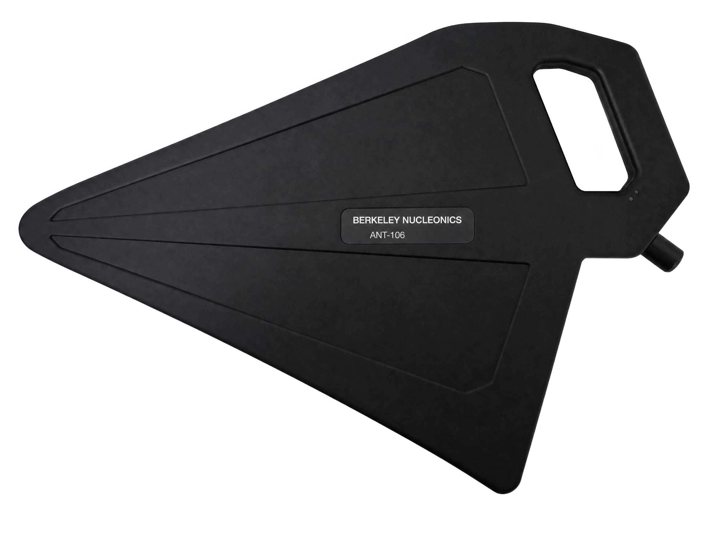
The ANT-100G is a handheld active directional antenna that operates from 500 MHz to 10 GHz, covering a wide span of test and survey requirements in a single instrument. Its directional pattern concentrates sensitivity in the look direction, which is exactly what direction finding and signal source localization demand. Point the antenna, watch the level, and walk the bearing down to the source.
An integrated high-performance broadband amplifier lifts system sensitivity well above what a passive antenna alone delivers. A switchable Amp Off / Amp On control lets you trade gain for dynamic range on the spot, so strong nearby emitters and faint distant ones are both within reach. The antenna identifies itself to compatible analyzers and loads its antenna factor automatically, which removes a manual calibration step and the errors that come with it.
The housing is light and ergonomic at 680 g total. That matters on a long survey. Operators can carry and aim the antenna for extended outdoor sessions without fatigue, which keeps a geolocation sweep moving rather than stopping for rest.
2Key Features
- Frequency range: 500 MHz to 10 GHz in a single antenna.
- Directional radiation pattern with 5 dBi passive gain (typ.) for clean bearing resolution.
- Low noise figure: 1.5 dB (typ.), so weak signals stay above the floor.
- Switchable amplifier: Amp Off / Amp On modes extend dynamic range to suit the scene.
- Automatic antenna factor loading across compatible ICX-FieldHawk analyzers for calibrated readings on connect.
- Light and portable: 680 g total weight.
- Ergonomic design built for extended outdoor use.
3Specifications
Values below reflect the ANT-100G (the 500 MHz to 10 GHz model). Specifications are preliminary and subject to verification against the published Berkeley Nucleonics datasheet.
| Parameter | ANT-100G |
|---|---|
| Frequency Range | 500 MHz to 10 GHz |
| Gain | 5 dBi (typ.) |
| Half-Power Beamwidth | 66° @ 6 GHz |
| Polarization Type | Linear |
| Front-to-Back Ratio | > 15 dB |
| VSWR | < 2.0 (typ.) |
| Amplifier Noise Figure | 1.5 dB (typ.) |
| Amplifier Gain | 20 dB (typ.) |
| Maximum Measurable Field Strength | 17 V/m @ 6 GHz (Amp Mode) |
| RF Connection | N (F), 50 Ω |
| Power Supply | USB Type-C; connects to host via USB Type-C to USB Type-A cable |
| Calibration Points | 191 (50 MHz step) |
| Dimensions (L x W x D) | 430 x 270 x 35 mm |
| Weight | 680 g |
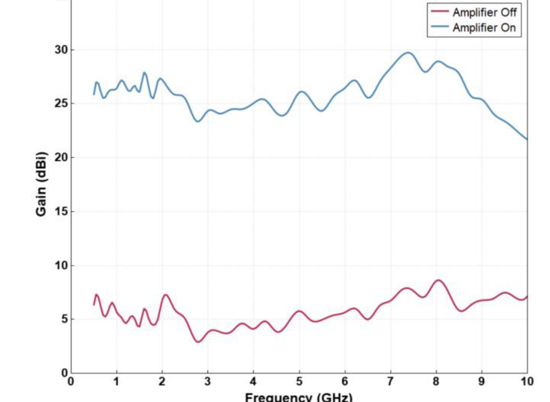
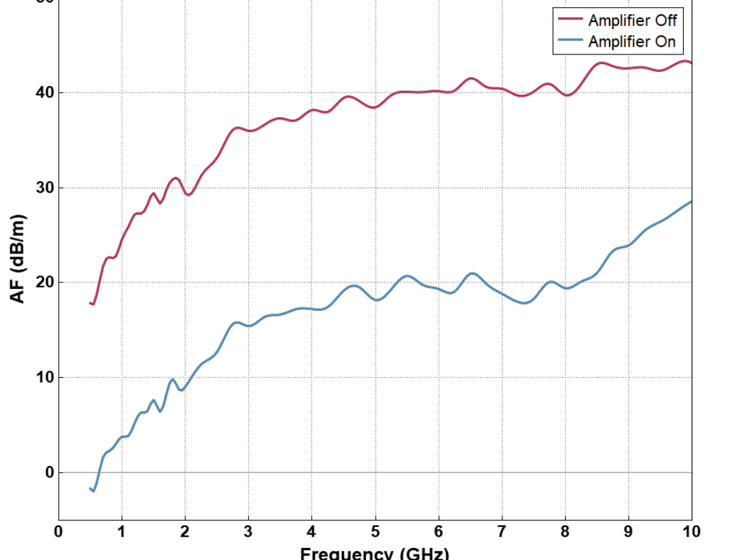
4Gain & Antenna Factor
The plots below show measured passive gain and antenna factor across the full band, with the amplifier off and on. Antenna factor is the value the analyzer applies to convert a measured port level into incident field strength, and it loads automatically when the ANT-100G is connected to a compatible ICX-FieldHawk analyzer.
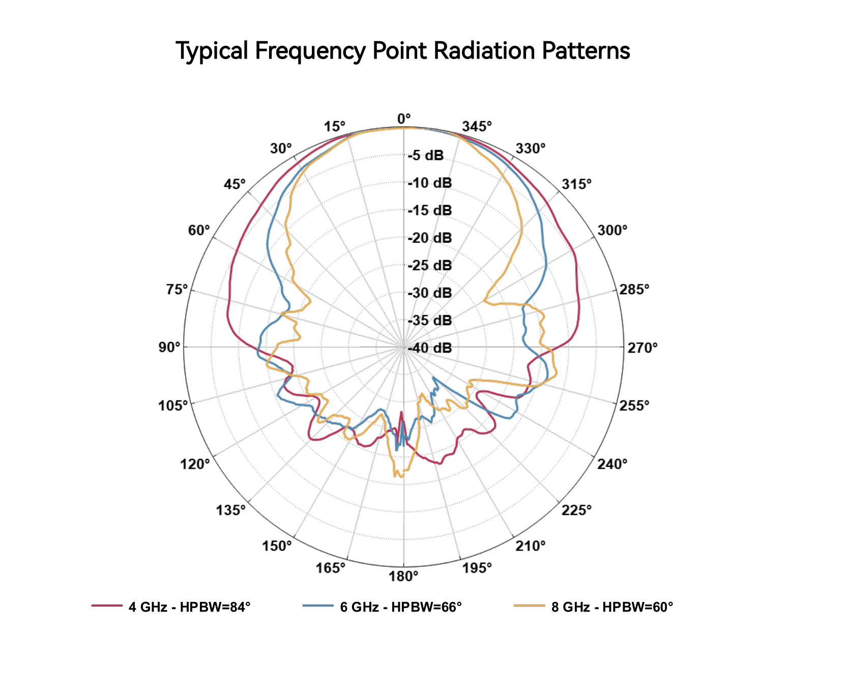
5Radiation Patterns
The directional pattern is what makes the ANT-100G useful for bearing work. The main lobe stays narrow across the band, and the back of the pattern is suppressed by more than 15 dB. As frequency rises the half-power beamwidth tightens, from roughly 84° at 4 GHz to 66° at 6 GHz and 60° at 8 GHz, which sharpens bearing resolution at the high end.
6Model Selection
Two active directional antennas share the same handheld platform and automatic antenna factor loading. The ANT-100G is the documented 500 MHz to 10 GHz model. The ANT-200G extends coverage further up the band for higher-frequency survey work; its frequency-dependent values are marked "verify" pending confirmation against the published datasheet.
| Specification | ANT-100G |
ANT-200G |
|---|---|---|
| Frequency Range | 500 MHz to 10 GHz | verify |
| Gain (typ.) | 5 dBi | verify |
| Polarization Type | Linear | Linear |
| Front-to-Back Ratio | > 15 dB | verify |
| Amplifier Noise Figure (typ.) | 1.5 dB | verify |
| Amplifier Gain (typ.) | 20 dB | verify |
| RF Connection | N (F), 50 Ω | N (F), 50 Ω |
| Power Supply | USB Type-C | USB Type-C |
| Automatic Antenna Factor | Yes | Yes |
| Weight | 680 g | verify |
7Pairing with ICX-FieldHawk
The ANT-100G is an accessory for the ICX-FieldHawk family of real-time spectrum analyzers. Connect the antenna over USB Type-C, and the analyzer reads the antenna identity and loads the correct antenna factor without operator input. From there the analyzer reports incident field strength directly, which is what a geolocation or compliance survey actually needs.
For direction finding, the workflow is simple. Set the analyzer to the frequency of interest, switch the amplifier on for weak signals or off for strong ones, then sweep the antenna in azimuth and read the peak. The narrow main lobe and high front-to-back ratio give a clear bearing. Take bearings from two or more positions and the intersection fixes the emitter location. The ANT-100G pairs with handheld, rugged, and USB ICX-FieldHawk configurations for field, vehicle, and bench deployments.
8In the Box & Connections
Connections
- RF output: Type N female, 50 Ω.
- Power and data: USB Type-C, connected to the host with a USB Type-C to USB Type-A cable.
Physical
- Dimensions: 430 x 270 x 35 mm (L x W x D).
- Weight: 680 g total.
- Calibration: 191 calibration points at a 50 MHz step.
9Support & Contact
For quotes, demonstrations, configuration help, or technical support, reach Berkeley Nucleonics directly. Our team can confirm specifications, recommend the right ICX-FieldHawk pairing, and arrange a field evaluation.
| Channel | Detail |
|---|---|
| info@berkeleynucleonics.com | |
| Phone | 800-234-7858 |
| Web | berkeleynucleonics.com |