HEL / ICF Front-End Timing
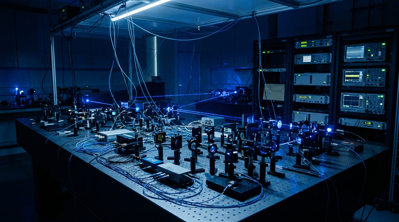
High-energy-laser (HEL) and inertial-confinement-fusion (ICF) systems begin at a front end where a low-power seed pulse is shaped, gated, and timed before it ever reaches an amplifier chain. That shaping happens in electro-optic (EOM) and acousto-optic (AOM) modulators, and the quality of the final shot depends on how cleanly those modulators are driven. The drive waveform sets the temporal pulse shape, gates the seed against the system master clock, and pre-distorts the pulse so the output of the amplifier chain lands on the target shape rather than the input shape. Get the front-end timing right and the rest of the chain has a clean foundation to work from. Get it wrong and no amount of downstream correction recovers the shot.
The audience for this work is narrow and demanding. ICF physicists need temporal pulse shapes that hold to picosecond-class timing across a multi-beam facility, and directed-energy engineers need modulator drive that stays aligned shot after shot. Both groups are working against a master clock that the whole facility shares, and both need every beamline to fire on the same timebase. A drive stage that wanders, even slightly, pushes the beams out of temporal overlap at the target and erodes the energy coupling the whole experiment is built to deliver.
The challenge
The hard part is that a front-end timing stage usually needs two things at once, and most generators deliver only one. First, it needs low-jitter synchronization to the facility master clock, so the seed pulse is gated at exactly the right instant relative to every other beamline and diagnostic. Second, it needs pulse pre-compensation, the ability to pre-distort the drive waveform so the nonlinear gain of the downstream amplifier chain produces the intended output shape rather than a saturated, front-loaded one.
Generators that excel at clock synchronization tend to be fixed-function timing instruments with little waveform flexibility. Generators that excel at arbitrary waveform shaping tend to free-run on their own internal clock with jitter far too high for a synchronized facility. Faced with that gap, facilities build custom timing chains by hand: a clock-distribution box, a separate shaping generator, an external amplifier, and a stack of cabling and trim adjustments that one engineer understands and no one else can service. The custom chain works until it drifts, and then the whole front end is down while someone rebuilds it.
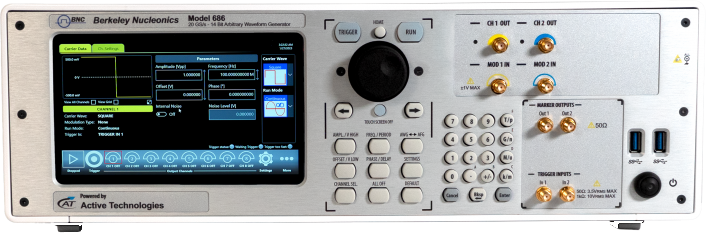
How the Model 686 solves it
The Model 686 closes that gap by putting synchronization and arbitrary shaping in one instrument, so the front-end timing stage is a single box on the bench rather than a hand-built chain.
It locks to the facility master clock with sub-2 ps trigger jitter, which keeps the gated seed pulse aligned to the shared timebase tightly enough for multi-beam ICF work. Where a shot needs more than one drive channel, or more than one 686, the units hold sub-100 fs channel alignment across separate instruments, so a multi-beamline front end stays coherent rather than drifting beam to beam.
Pulse pre-compensation lives in firmware. The drive waveform can be pre-distorted on the instrument to counteract the nonlinear gain of the downstream amplifier chain, so the seed is shaped to produce the intended output rather than the intended input. That correction stays with the instrument and the stored waveform, not in an external box that has to be re-trimmed.
The output drives modulators directly. At 5 Vpp into 50 ohm, the 686 supplies enough amplitude for typical EOM and AOM drive stages without an external amplifier in the path, which removes a source of added jitter, drift, and distortion. Every amplifier dropped from the chain is one less component to characterize, temperature-compensate, and re-trim over a campaign. Deep memory of up to 9 Gpts holds long, finely sampled waveforms and lets a facility stage a full schedule of shots in memory, so the front end is loaded once and steps through the run rather than reloading between shots. That depth also leaves room for fine temporal structure: a single stored waveform can carry both the coarse pulse envelope and the picosecond-scale features a shaped ICF pulse demands, without trading sample density for record length.
Recommended configuration
For a single beamline front end, a two-channel Model 686 covers the common case: one channel gates and shapes the EOM drive, the second handles an AOM stage or a companion diagnostic trigger. Lock the instrument to the facility master clock and apply the firmware pulse pre-compensation profile measured for the amplifier chain.
For multi-beamline facilities, use a four-channel Model 686, or several units in a multi-unit sync configuration, to hold the front end coherent across beamlines at sub-100 fs channel alignment. In every case drive the EOM and AOM stages directly from the 5 Vpp outputs and keep the full shot schedule resident in the deep waveform memory.
Talk to an application engineer
Berkeley Nucleonics can help you match a Model 686 configuration to your HEL or ICF front-end timing stage. Call 800-234-7858 or email info@berkeleynucleonics.com.
For a quick question, chat with an engineer at berkeleynucleonics.com.