The fastest 14-bit arbitrary waveform generator in the Berkeley Nucleonics line: sample rates from 1 Sa/s to 20 GS/s, 10 GHz of generation bandwidth, up to 9 Gpts of record length, and two or four analog channels with up to 32 optional digital channels in one instrument.
Model 686 · Document rev. A · Specifications typical, verify against published datasheet
1Overview
The Berkeley Nucleonics Model 686 is the fastest 14-bit arbitrary waveform generator in the line. A programmable sample rate from 1 Sa/s to 20 GS/s, 14-bit vertical resolution, and up to 9 Gpts of waveform memory let a single instrument reproduce nearly any signal, ideal or distorted, standard or fully custom. Two or four analog channels are available, each capable of 5 Vpp single-ended or 1.25 Vpp differential into 50 ohm, with rise and fall times as short as 50 ps and a 6.5 GHz sine output. The instrument reaches 10 GHz of generation bandwidth, so the real-world edges and pulse shapes demanded by frontier test cases come straight off the front panel.
The 686 was built for mixed-signal work. Four-channel models add up to 32 synchronized digital channels through an optional license, so analog stimulus and digital patterns run together for debugging and validating high-speed digital designs. When one chassis is not enough, up to four instruments synchronize over a dedicated bus to form a single 16 analog and 128 digital channel generator, with intra-chassis timing held tight across the group.
Operation is organized around three software modes that share one touch-driven platform. Simple Rider AFG provides a DDS function-generator interface for fast, conventional waveform setup. TrueArb is a variable-clock arbitrary mode for long, sequenced waveforms with loops, jumps, and conditional branches. The optional Pulse Pattern Generator (PPG) produces PRBS and custom serial patterns up to 6.5 Gbaud with arbitrarily shaped bit transitions. A 7-inch capacitive touchscreen, front-panel buttons, and a control knob handle local operation, while LAN, USB-TMC, and GPIB cover remote control and automation.
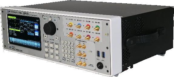
Model 686, three-quarter view showing the 7-inch touchscreen, control knob, and front-panel SMA output bank.
2Key Features
Up to 20 GS/s, 14-bit. Sample rate programmable from 1 Sa/s to 20 GS/s with 14-bit vertical resolution for exceptional signal integrity.
Deep memory. Arbitrary waveform memory up to 9 Gpts for long, complex playback without re-loading.
Mixed-signal generation. 2 or 4 analog channels with up to 32 synchronized digital channels for debugging and validating digital designs.
Three operation modes. Simple Rider AFG (DDS function generator), TrueArb (variable-clock arbitrary AWG), and PPG (pulse and serial pattern generator, optional).
High-rate digital outputs. Up to 10 Gb/s per channel in programmable CML; a CML-to-LVTTL adapter is available.
Advanced sequencer. Up to 16,384 user-defined waveform entries build complex signal scenarios with efficient memory use.
Fast edges, high amplitude. 5 Vpp output with rise and fall times to 50 ps and 6.5 GHz sine, a strong amplitude-and-bandwidth combination.
Synchronization to 16 / 128 channels. Up to four units lock together for 16 analog and 128 digital channels over a dedicated sync bus.
Windows platform. 7-inch capacitive touchscreen, front-panel buttons and knob, Windows 10, and a compact 3U 19-inch rackmount form factor.
Standard remote interfaces. LAN, USB-TMC, and GPIB for instrument control and automated programming.
3Front & Rear Panels
The front panel groups the touchscreen, control knob, and numeric keypad on the left, with the analog output bank, marker outputs, and trigger inputs on the right. The rear panel carries the reference and sync clock connectors, the digital output pods, the QSFP synchronization links, the computing ports, and AC input.
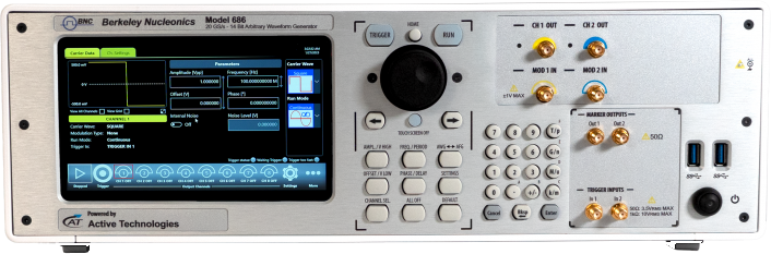
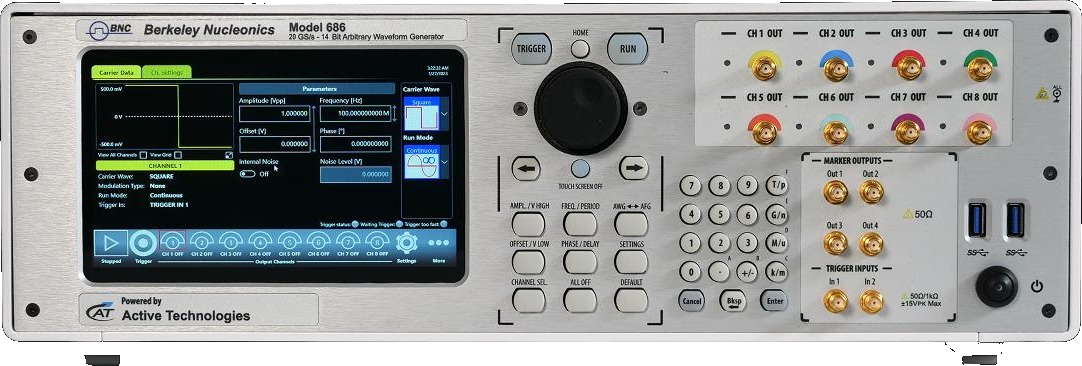
Model 686 front panel: 7-inch touchscreen and knob, AFG keypad, CH OUT SMA bank, marker outputs, and trigger inputs.
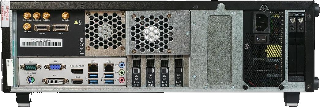
Model 686 rear panel: reference and sync clock SMA connectors, sync I/O, computing ports, digital output pods, and AC inlet.
4Software Modes
The 686 presents one touch-driven platform with three operating interfaces. Each is purpose-built for a class of signal generation, and all share the same instrument hardware.
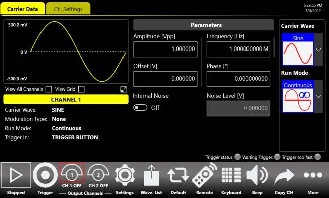
Simple Rider AFG: Function Generator Mode
The AFG interface puts the capabilities of a modern function generator at the user's fingertips, with a tablet-style touch layout. A swipe gesture exposes the output waveform parameters, a touch-friendly numeric keypad speeds data entry, and shortcuts and intuitive icons streamline setup. Standard waveforms include sine, square, pulse, ramp, noise, DC, Sin(x)/x, Gaussian, Lorentz, exponential rise, exponential decay, and Haversine.
Simple Rider AFG: function-generator mode with carrier waveform, amplitude, frequency, phase, and run-mode controls.
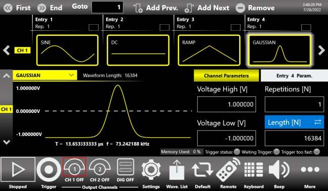
Simple Rider TrueArb: AWG Mode
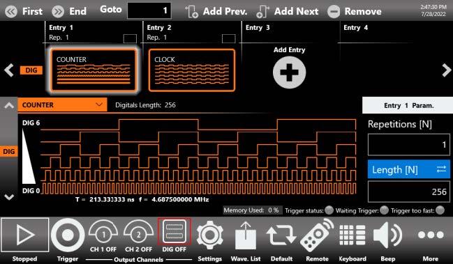
TrueArb lets users define complex waveforms with up to 16,384 sequence entries of analog waveforms and digital patterns, and lay out execution flow with loops, jumps, and conditional branches. Waveform memory of up to 9 GSamples per channel, combined with sequence repeats up to 4,294,967,294, makes the 686 suited to the most demanding scenarios. Synchronized digital output paired with the analog signals provides an effective tool for troubleshooting and validating digital designs.
TrueArb analog sequencer: per-entry waveform selection (sine, DC, ramp, Gaussian) with repetition and length control.TrueArb digital sequencer: synchronized digital pattern entries shown alongside the analog timeline.
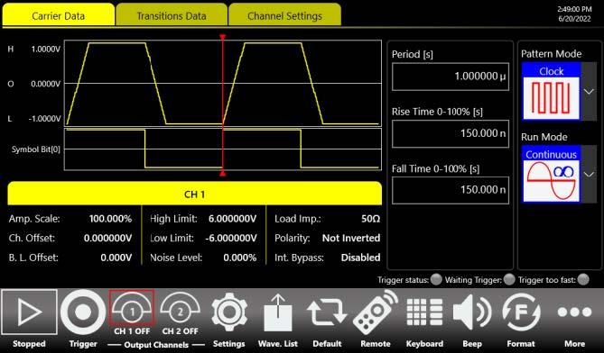
Simple Rider PPG: Pulse Pattern Generator Mode
The optional PPG interface creates pattern scenarios in a few screen touches. It generates PRBS patterns and custom patterns up to 12 MSymbols, where bit transitions can take arbitrarily user-defined shapes, at rates up to 6.5 Gbaud. The architecture supports several generation modes and can modulate patterns with internal or external signals to introduce controlled impairments such as jitter and ripple.
Simple Rider PPG: pattern carrier and transition data with programmable rise and fall times and run mode.
5General Specifications
All specifications are typical unless noted otherwise. Guaranteed performance refers to a calibrated instrument stored for at least 2 hours within the operating temperature range of 41 to 104 F (5 to 40 C), after a 45-minute warm-up, and within 18 F (10 C) of the auto-calibration temperature.
Parameter
686-2C-SE / 686-4C-SE
686-2CD / 686-4CD
Operating modes
AFG mode, TrueArb mode, SPG / PPG mode (optional)
Analog channels
2 (2-channel models) or 4 (4-channel models)
Markers
2 (2-channel models) or 4 (4-channel models)
Digital channels
Up to 32 (4-channel models, optional license)
Output type
Single-ended, DC coupled
Differential, DC coupled
Output impedance
50 ohm single-ended
50 ohm single-ended / 100 ohm differential
Connectors
SMA on front panel
Vertical resolution
14-bit
DC Amplitude
Parameter
686-2C-SE / 686-4C-SE
686-2CD / 686-4CD
Amplitude range
±2.5 V (into 50 ohm)
±0.625 V SE (into 50 ohm); ±1.25 V diff. (into 100 ohm)
Resolution
500 µV nom, 5 digits
100 µV nom, 5 digits
Amplitude accuracy
±(1.5% of |setting| + 15 mV)
±(1% of |setting| + 2 mV)
DC Baseline Hardware Offset (Common-Mode Offset)
Parameter
686-2C-SE / 686-4C-SE
686-2CD / 686-4CD
Resolution
Less than 4 mV or 4 digits
Range (50 ohm into 50 ohm)
-2.5 V to +2.5 V
-2 V to +2 V
Range (50 ohm into high-Z load)
-2.5 V to +2.5 V
-4 V to +4 V
Accuracy (50 ohm into 50 ohm), guaranteed
±(1% of |setting| + 15 mV)
±(1% of |setting| + 5 mV)
AC accuracy (1 kHz sine, 0 V offset, >5 mVpp, 50 ohm), guaranteed
±(1% of setting [Vpp] + 5 mV)
Amplitude and AC accuracy specifications are guaranteed across 0% to 80% of full-scale output.
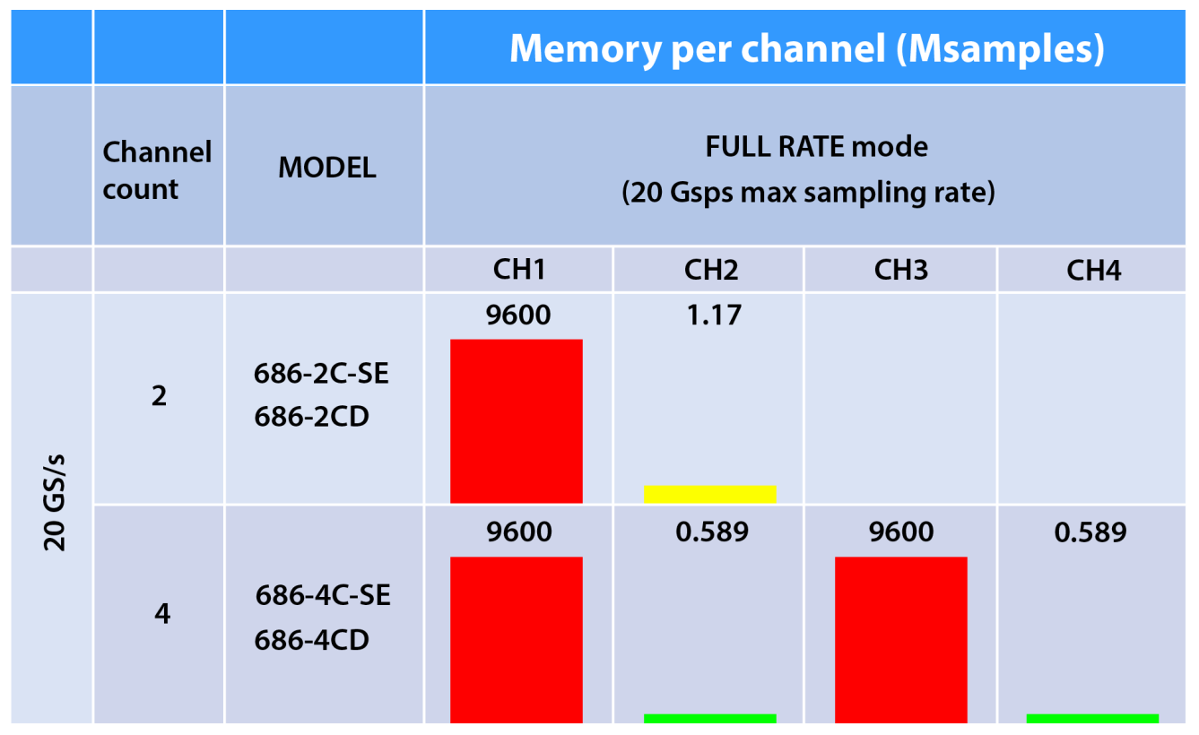
6TrueArb (Baseband) Specifications
Parameter
Specification
Operating modes
Full Rate mode (variable clock), Half Rate mode (variable clock)
SMA rear panel, 50 ohm AC coupled, 1 Vpp into 50 ohm
10Digital Outputs
Parameter
Specification
Connectors
Mini-SAS HD on rear panel (custom pin-out), 4 connectors
Number of outputs
32 bits
Output impedance
100 ohm differential
Output type
CML with programmable peak-to-peak amplitude
Maximum update rate
10 Gb/s per channel
Memory depth
4.5 Gbit per digital channel
Digital channels are available on 4-channel models through an optional license (8, 16, or 32 channels). The AT-DTTL8 adapter probe converts 8 bits of LVDS to LVTTL, and the AT-LVDS-SMA8 cable breaks a Mini-SAS HD pod out to SMA.
11Auxiliary Input and Output
Parameter
Specification
Sync in / out
QSFP connector on rear panel (custom pinout)
Modulation input (MOD_IN)
SMA front panel, 50 ohm, ±1 V window; 2 (2-ch) or 4 (4-ch) connectors
Marker output
SMA front panel, 50 ohm; voltage window -0.5 V to 1.65 V; amplitude 100 mVpp to 2.15 Vpp
Marker accuracy / resolution
±(5% setting + 25 mV) / 1 mV
Marker max update rate (TrueArb)
20 Gb/s; > 4 Gb/s at 1 Vpp swing
Marker rise/fall (10% to 90%, 2 Vpp)
< 150 ps
Trigger / event inputs
SMA front panel; 50 ohm or 1 kohm; 2 (2-ch) or 4 (4-ch)
Trigger input range
±3.5 V (50 ohm); ±10 V (1 kohm)
Trigger threshold control
-8 V to 8 V, 10 mV resolution, ±100 mV accuracy
Trigger minimum pulse width (1 Vpp)
1 ns
Trigger programmable delay
0 ps to 2418 ps, 78 ps resolution
12Power & System
Parameter
Specification
Source voltage and frequency
100 to 240 VAC ±10% at 45 to 66 Hz
Max power consumption
250 W
Operating temperature
41 to 104 F (5 to 40 C)
Non-operating temperature
-4 to 140 F (-20 to 60 C)
Operating humidity
5% to 80% RH, non-condensing (de-rates at upper temperature)
Operating altitude
9,842 ft (3,000 m) max at or below 77 F (25 C)
Safety
EN 61010-1
EMC
EN 61326-1:2013
Display
7-inch, 1024 x 600, capacitive touch LCD
Operating system
Windows 10
Processor / memory / storage
Intel Pentium Gold G6400 4 GHz or better / 32 GB or better / 1 TB SSD or better
External dimensions
17.5 x 5.3 x 12.6 in (445 x 135 x 320 mm), 3U 19-inch rackmount
Weight
Max 26.45 lb (12 kg)
Remote interfaces
LAN (10/100/1000BaseT, RJ45), USB-TMC, GPIB
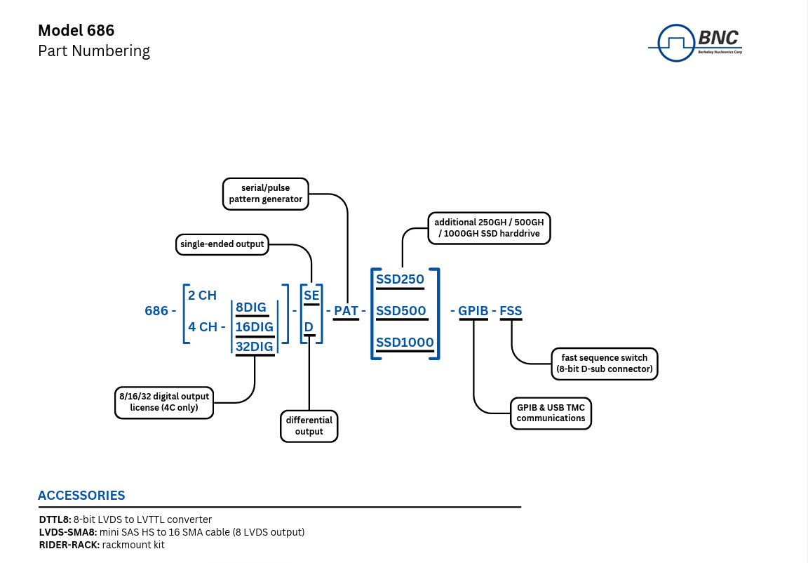
13Ordering & Part Numbering
The base instrument is selected by channel count and output type. Single-ended models deliver 5 Vpp into 50 ohm; differential models deliver 2.5 Vpp differential, equivalent to 1.25 Vpp single-ended. Digital channels, the serial pattern generator, fast sequence switch, and synchronization are added as options.
16-channel digital license (4-channel models only)
686-32DIG
32-channel digital license (4-channel models only)
686-FSS
Fast Sequence Switch
686-WAR
3-year warranty extension
RIDER-MINI-SAS-HD
Mini-SAS HD cable for digital probe, 8 differential signals (4-channel models only)
RIDER-686-SYNC
Synchronization cable for all 686 models
GP-IB / USB-TMC
GPIB and USB-TMC ports for remote control
Accessories
Item
Description
DTTL8 (AT-DTTL8)
8-bit LVDS to LVTTL converter probe (4-channel models only)
LVDS-SMA8 (AT-LVDS-SMA8)
Mini-SAS HD to 16 SMA cable, 8 differential bits (4-channel models only)
RIDER-RACK
Rackmount kit for the Rider instrument system
14Applications
The Model 686 pairs fast edges, high amplitude, and deep sequencing to emulate real-world signals across research, communications, and defense work.
Quantum and QKD. Pulse shaping for quantum sensing and quantum key distribution, cold-atom experiments, and manipulation of nitrogen-vacancy color centers in diamond.
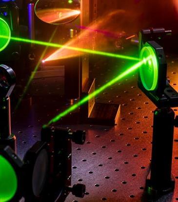
Optics and photonics. Driving electro-optic and acousto-optic modulators, pulsed laser diodes, and quantum-optics emitters with narrow, high-amplitude pulses.
Radar and electronic warfare. RF, IF, and IQ waveform synthesis, modulated radar emulation, and complex EW scenario generation through the advanced sequencer.
LiDAR and automotive. Physical-layer, transmitter, receiver, and channel testing for camera, LiDAR, radar, and ultrasound sensor systems.
High-speed serial. PRBS and multi-level PAM stimulus for SATA, USB, and PCI Express compliance and debug work.
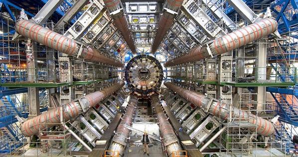
High-energy and pulsed-power timing. Signal emulation for accelerators, tokamaks, and synchrotrons, including pulsed electron-beam, X-ray source, and HEL/ICF timing applications.
Optics and photonics: driving modulators and pulsed laser sources on an optical bench.Quantum sensing and quantum key distribution for secure communication.
Advanced research: signal emulation for accelerators, tokamaks, and synchrotrons.Semiconductor test: high-speed serial stimulus and fast-edge device characterization.
Aerospace and defense: radar, LiDAR, and sonar emulation and avionics testing.
15Software & Support
The Model 686 is programmed with the 686 SDK, which exposes the instrument's modes and sequencing to custom test software. Download the 686 SDK to integrate the generator into an automated test framework over LAN, USB-TMC, or GPIB.
For a quote, configuration help, or application support, reach the Berkeley Nucleonics team.