Serial Pattern Generation (SPG)
Serial pattern generation is the act of producing a defined sequence of bits, symbol by symbol, on one or more output channels so that a digital device, a serial link, or a logic block can be driven, stressed, and characterized. A serial pattern can be a fixed word, a long pseudo-random bit sequence (PRBS), a hand-built custom stream, or a deliberate stress pattern designed to push a receiver toward its limits. In every case the value of the pattern depends on more than the bits alone. It depends on how cleanly each edge is shaped, where each voltage level sits, and how precisely the channels line up against one another. That is the gap between a logic-only pattern source and a serial pattern generator built on an arbitrary waveform engine.
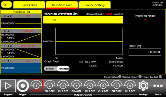
The SPG mode on the Berkeley Nucleonics arbitrary waveform generators closes that gap. It combines the bit-level control of a data pattern generator with the analog control of an arbitrary waveform generator, so the user programs the pattern and the signal that carries it in the same instrument. Each symbol is placed on a precise timebase, each transition is given a defined shape, and each channel is held in a known relationship to the others. The result is a serial stream that looks the way a real interface signal looks, not an idealized square wave, which is exactly what is needed to expose timing margin, level sensitivity, and edge-rate effects in the device under test.
Why it matters
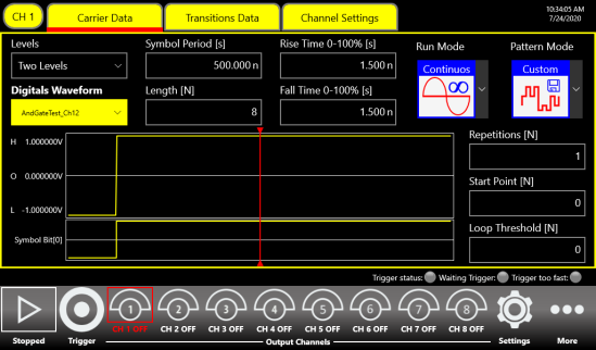
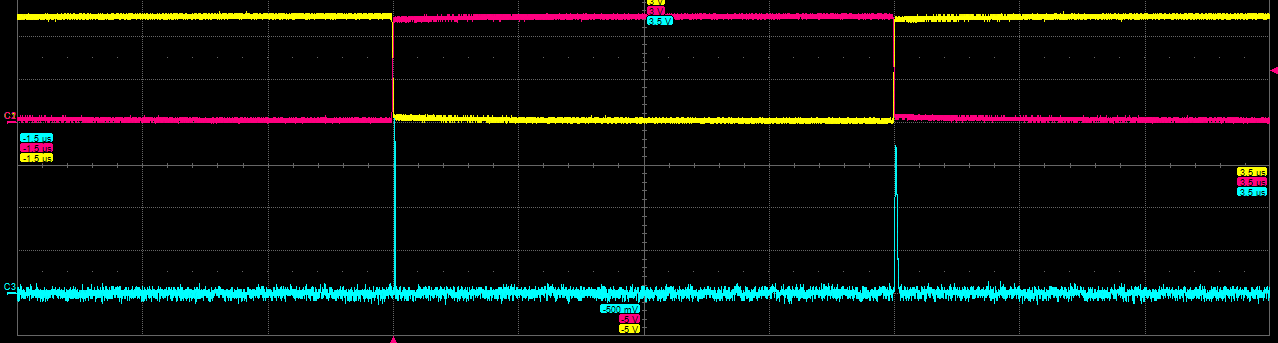
Digital and high-speed serial interfaces fail in the analog domain. A receiver that passes with clean square-wave stimulus can still fail when edges slow down, when overshoot appears on a transition, or when two inputs switch at slightly different times. Characterizing that behavior requires a stimulus that can be shaped on purpose. With SPG, the engineer sets the bit pattern to exercise a protocol or a logic function, then adjusts rise and fall time, overshoot, voltage window, and channel-to-channel skew to reproduce the conditions the device will see in the field. PRBS and custom stress patterns extend the same idea to serial links, where the goal is to walk a receiver up to its margin and watch where the errors begin.
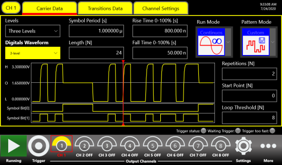
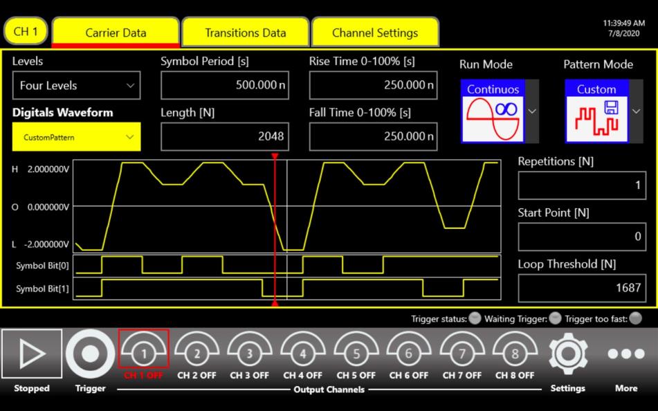
The multilevel capability matters here as much as the bit rate. Each channel can define up to four independent voltage levels, so beyond a simple logical 0 and 1 the instrument can emulate a tristate buffer or a weak 0 on an undriven bus. That lets a single pattern reproduce bus contention, level shifting between voltage standards, and the multiplexed address and data behavior found on real boards. For semiconductor and logic-gate work, the same control accelerates reliability and failure-analysis studies by reducing the time from setup to a running characterization.
Capabilities
The SPG mode is defined by the analog front end behind it. Vertical resolution is 14 bits and the analog bandwidth is 318 MHz, which together give the edge fidelity needed to shape each transition as a clean linear ramp, an RC transient, or an edge with a defined overshoot. The amplitude reaches up to 12 Vpp into 50 ohms (24 Vpp into an open load), and a programmable baseline offset shifts the voltage window by up to plus or minus 6 V into 50 ohms (plus or minus 12 V into an open load). Used together, those let the instrument place a 0 to 12 V signal into 50 ohms, covering common logic-family thresholds directly.
Pattern depth runs up to 2 Mbits, deep enough to hold long custom streams and PRBS sequences without falling back to a short repeating loop. A selectable header lets an initial portion of the pattern play once while the remainder repeats, which is useful for preamble-then-payload structures. Edge timing is set per transition, and because the channel timebase is built on direct digital synthesis (DDS), the skew between channels can be controlled to roughly 1 ps resolution. Symbol rates reach up to 300 mega-symbols per second. Generation runs continuously, in triggered burst for a selected number of repetitions, or with AM, FM, PM, FSK, or PSK modulation applied to the pattern.
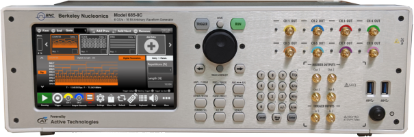
Multi-channel work is native to the platform. Each unit carries eight independent analog channels, and up to four units synchronize to build a single 32-channel system on a shared timebase. That headroom suits wide buses, multi-input logic gates, and multi-lane serial test where every channel has to agree on the same definition of time. The pattern and its edges are imported and managed through a touchscreen interface, and for an automated test bench the instrument accepts SCPI commands from an external controller.
Supported models
SPG mode is available on the Berkeley Nucleonics arbitrary waveform generators that share the Rider analog architecture. On the Model 685 / 675 Rider platform, the mode combines the multilevel pattern engine with the high-amplitude, edge-shaped analog front end described above, which is what makes these units a direct fit for digital logic and serial interface characterization. The Model 686 carries the same pattern-generation capability forward on the current high-performance platform, for work that benefits from its deeper memory and tighter synchronization across units.
The Model 675 and 685 share an interface and synchronization scheme, so a system can scale from a single eight-channel unit to a synchronized 32-channel bench without changing how patterns are built. Choose the configuration that matches the channel count, amplitude, and symbol rate the device under test demands.
Talk to an application engineer
Berkeley Nucleonics can help you match a Model 685, Model 675, or Model 686 configuration to your serial pattern, PRBS, and digital interface test requirements. Call 800-234-7858 or email info@berkeleynucleonics.com.
For a quick question, chat with an engineer at berkeleynucleonics.com.