ICX-FH-U-PM Rev 1.2 against the BNC document numbering scheme; the option-34 omnidirectional and option-35 active directional antenna part numbers if BNC assigns ANT-series codes such as ANT-100G (verify); and the SpecICX-gen3 release build strings quoted under test conditions (verify they carry to BNC release builds).1Overview
The ICX-FieldHawk-U is a USB real-time spectrum analyzer that delivers bench-class RF performance in a compact, integration-ready package. Its high-performance superheterodyne receiver carries up to 14 stages of preselection filtering, which gives it excellent noise performance, wide dynamic range, strong interference immunity, and fast analysis speed at a cost that scales well across volume deployments.
The compact form factor makes the analyzer easy to embed into larger systems while preserving high RF performance and spectral purity. That combination suits it to space-constrained and cost-constrained applications, from production test racks to distributed monitoring nodes.
All three models share a unified API. Hardware migration across the family needs no code changes. The API supports C/C++, C#, Python, MATLAB, Qt, and LabVIEW on both Windows and Linux, and the instrument honors the standard SCPI protocol.
Standard measurement functions are broad out of the box. They include channel power, occupied bandwidth, XdB bandwidth, harmonic measurement, AM and FM demodulation, and automatic phase noise measurement. A built-in GNSS receiver supports frequency calibration, and a single USB 3.0/2.0 Type-C interface carries both power and data.
2Key Features
- High-performance superheterodyne receiver with up to 14-stage preselection filters
- Frequency range: 9 kHz to 4.5, 6, or 9 GHz depending on model
- 1 GHz DANL: -168 dBm/Hz
- 9 GHz DANL: -167 dBm/Hz
- 1 GHz phase noise: < -110 dBc/Hz at 10 kHz offset
- 1 GHz phase noise measurement: < -125 dBc/Hz at 10 kHz offset
- Analysis bandwidth: 50 MHz, or 100 MHz with OPT-120
- Sweep speed: > 1 THz/s at RBW = 250 kHz
- IF and image rejection: > 95 dBc
- Built-in GNSS, supports frequency calibration
- USB 3.0/2.0 Type-C interface
- Provides rich APIs and example programs
- Supports Windows 11/10/8/7 (x86, x64)
- Supports Debian 12/11/10 (x64, AArch64)
- Supports Ubuntu 24.04/22.04/20.04/18.04 (x64, AArch64)
- Supports the standard SCPI protocol
3Operating Modes
SpecICX-gen3 offers multiple primary operating modes: Standard Spectrum Analysis, IQ Streaming, Power Detection Analysis, Real-Time Spectrum Analysis, Phase Noise Measurement, Basic Vector Modulation Analysis (OPT-410), Pulse Analysis (OPT-420), Harmonic Analysis, and Mapping.
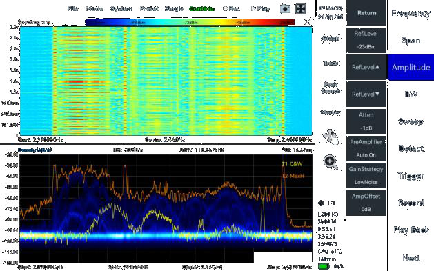
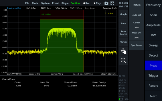
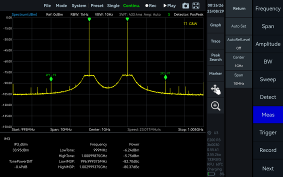
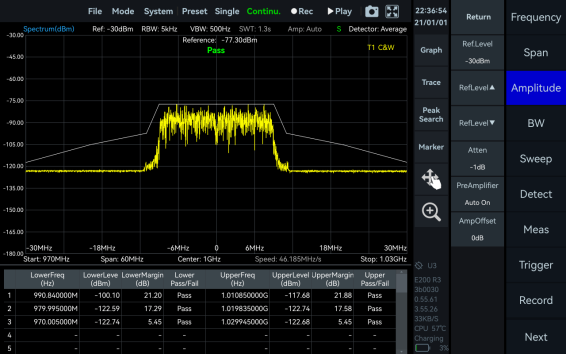
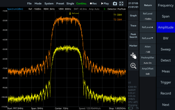
Standard Spectrum Analysis
This mode provides a wide range of measurement functions, including full-span spectrum sweep, channel power, OBW, ACPR, IM3, and SEM. It also supports spectrum recording and playback. Combined with auxiliary tools such as signal tracking, peak table, and amplitude correction, it delivers a one-stop platform for comprehensive spectrum checks.
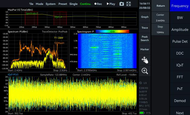
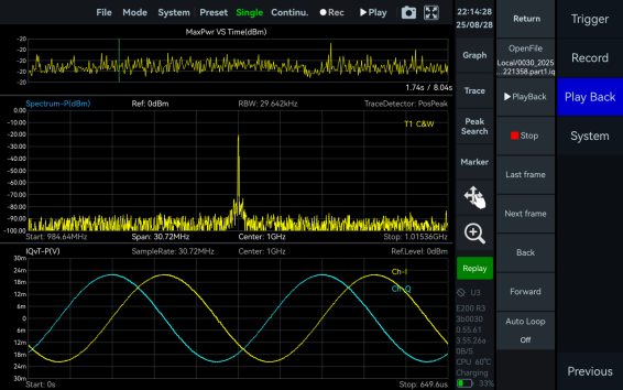
IQ Streaming
This mode supports up to 100 MHz of analysis bandwidth and allows IQ data acquisition through multiple trigger methods. It provides IQ time-domain waveform display, spectrum and spectrogram views, AM and FM demodulation, and digital down conversion (DDC).
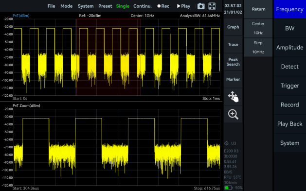
Power Detection Analysis
This mode enables detection and analysis of time-domain signals within the analysis bandwidth. It suits applications focused on in-band power-versus-time relationships, such as pulse signal measurements.
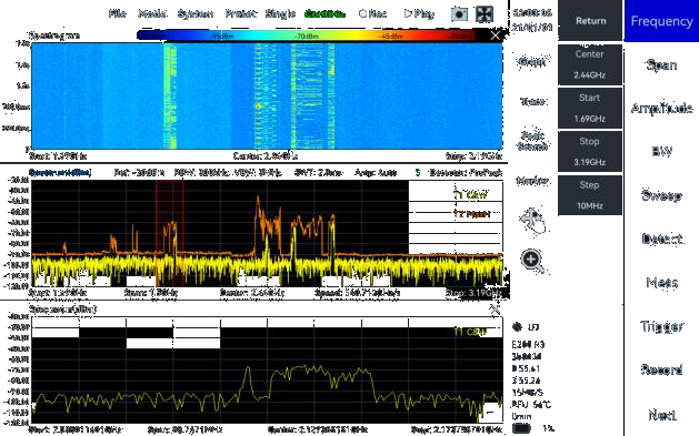
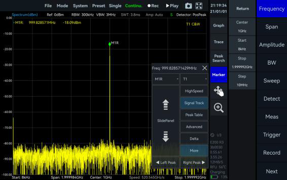
Real-Time Spectrum Analysis
This mode is powered by a high-speed FPGA-based FFT engine. It features strictly gapless and overlap-free FFT, achieving true real-time monitoring across the full bandwidth.
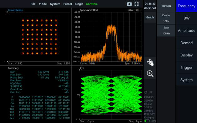
Basic Vector Modulation Analysis (OPT-410)
This mode supports 2ASK, 2FSK, 4FSK, GMSK, BPSK, QPSK, 8PSK, 16QAM, 64QAM, 128QAM, and 256QAM signals.
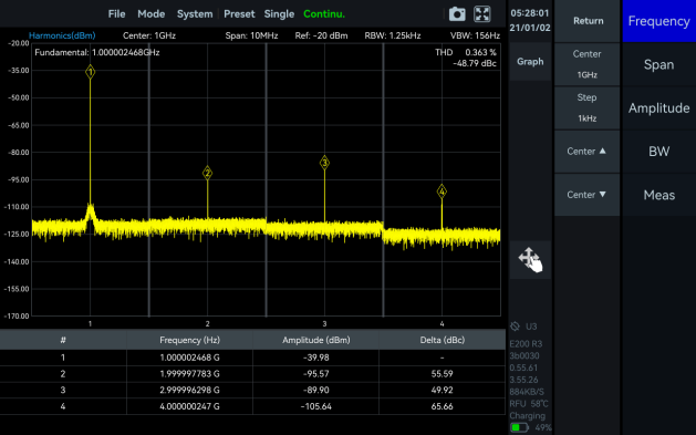
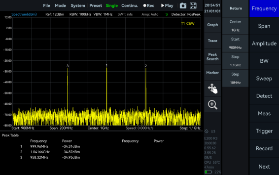
Harmonic Analysis
This mode supports detection and measurement of up to 10 harmonic components, including harmonic peaks, harmonic channel power, and total harmonic distortion.
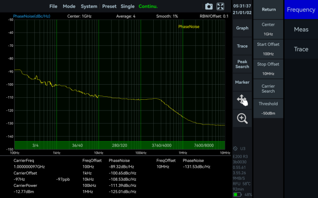
Phase Noise Measurement
This mode supports offset ranges from 1 Hz to 10 MHz for evaluating carrier phase stability. A built-in automatic carrier search function locates the target carrier quickly, with no manual adjustment.
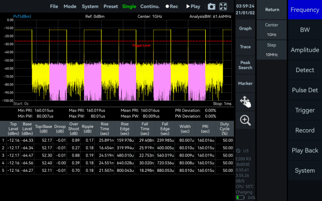
Pulse Analysis (OPT-420)
This mode supports measurement of pulse signals with a pulse width of 32 ns or more, displaying key parameters such as Top level (dBm), Base level (dBm), Top/Base, Droop, Overshoot, Ripple, Rise and Fall Time, Rise and Fall Edge, Width, PRI, and Duty Cycle.
Mapping
This mode integrates GPS positioning data to generate heat maps and other visual charts. It displays key information such as Channel Power, Occupied BW, Time, Coordinates (latitude and longitude), Altitude, Pixel Position, and Azimuth within a defined area. It suits fields such as radio monitoring and interference analysis.
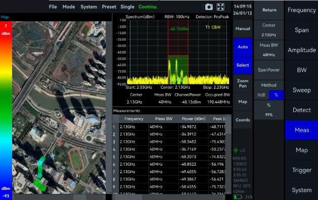
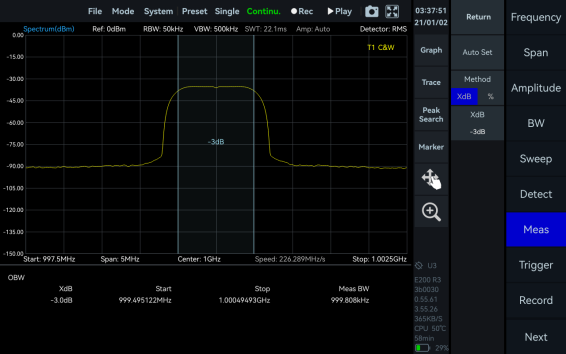
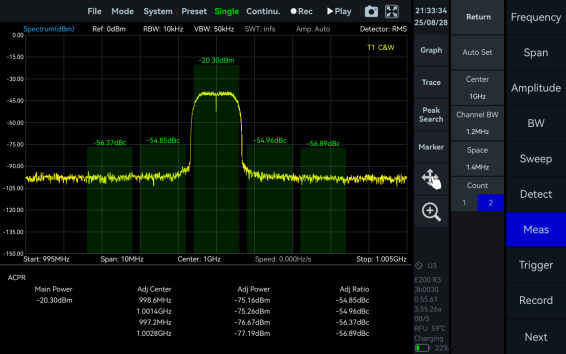
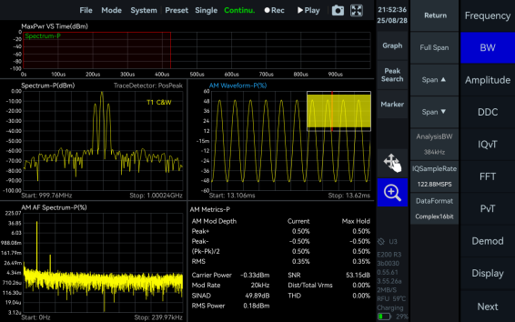
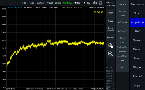
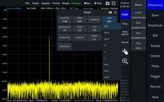
4Measurement Functions
The analyzer ships with a comprehensive set of standard measurement functions in SpecICX-gen3. The screenshots below show each function in use.
5Model Selection
The ICX-FieldHawk-U family spans three frequency tiers on a common platform. Pick the model by maximum frequency. All three share the same form factor, unified API, and standard measurement set, so a migration up the range needs no software change.
| Specification |  ICX-045U ICX-045U |
ICX-060U |
ICX-090U |
|---|---|---|---|
| Frequency range | 9 kHz to 4.5 GHz | 9 kHz to 6 GHz | 9 kHz to 9 GHz |
| Analysis bandwidth | 50 MHz, or 100 MHz with OPT-120 | ||
| Sweep speed (RBW = 250 kHz) | > 1 THz/s | ||
| Best DANL (typical) | -168 dBm/Hz at 1 GHz | ||
| Interface | USB 3.0/2.0 Type-C, single connection for power and data | ||
| Built-in GNSS | Yes, supports frequency calibration | ||
6Frequency
| Frequency | ICX-045U | ICX-060U | ICX-090U |
|---|---|---|---|
| Frequency range | 9 kHz to 4.5 GHz | 9 kHz to 6 GHz | 9 kHz to 9 GHz |
| Reference clock | Internal or external; manual correction or GNSS calibration is available | ||
| Frequency accuracy, TCXO (std.) | < 0.5 ppm, manual correction available | ||
| Frequency accuracy, OCXO (opt01) | < 0.2 ppm, manual correction available | ||
| Frequency correction via GNSS | < 0.05 ppm when GNSS is locked | ||
| Aging and temperature stability, TCXO (std.) | < 1 ppm/year, < 1 ppm | ||
| Aging and temperature stability, OCXO (opt01) | < 1 ppm/year, < 0.15 ppm | ||
| Built-in GNSS 1PPS accuracy | ± 100 ns | ||
7Spectrum Purity
SSB Phase Noise (dBc/Hz), Guaranteed / Typical
| Offset | 1 GHz | 4.5 GHz | 6 GHz | 9 GHz |
|---|---|---|---|---|
| 100 Hz | -85 / -88 | -78 / -81 | -75 / -78 | -74 / -77 |
| 1 kHz | -97 / -99 | -90 / -93 | -86 / -89 | -88 / -91 |
| 10 kHz | -110 / -112 | -103 / -106 | -100 / -103 | -99 / -102 |
| 100 kHz | -114 / -115 | -104 / -107 | -104 / -107 | -99 / -102 |
| 1 MHz | -131 / -132 | -119 / -122 | -118 / -121 | -116 / -119 |
Residual Response (dBm), Guaranteed / Typical
Conditions: RBW = 1 kHz.
| Band | R.L. 0 dBm | R.L. -50 dBm |
|---|---|---|
| 9 kHz to 100 MHz | -90 / -94 | -115 / -117 |
| 100 MHz to 4.5 GHz | -90 / -95 | -120 / -128 |
| 4.5 GHz to 6 GHz | -90 / -96 | -120 / -130 |
| 6 GHz to 9 GHz | -90 / -98 | -120 / -129 |
Rejection & Spurious
| Parameter | Specification |
|---|---|
| Image rejection | > 90 dBc, > 95 dBc (typical) |
| IF rejection | > 90 dBc, > 95 dBc (typical) |
| Local oscillator related spurious | < -65 dBc at center frequency ± (N/M) × 100 MHz, N, M = 1, 2, 3, 4, 5 ... |
IIP3 / IIP2 (dBm), Typical
| Carrier frequency | 1 GHz | 4.5 GHz | 6 GHz | 9 GHz |
|---|---|---|---|---|
| R.L. = 20 dBm | 42 / 80 | 37 / 80 | 32 / 80 | 36 / 80 |
| R.L. = 0 dBm | 23 / 80 | 22 / 80 | 20 / 80 | 14 / 80 |
| R.L. = -20 dBm | 3 / 60 | 3 / 45 | -1 / 45 | -5 / 45 |
8Amplitude
| Parameter | Specification |
|---|---|
| Max. input power (CW) | 23 dBm, 50 MHz to maximum frequency with preamplifier off; 10 dBm, 9 kHz to 50 MHz or with preamplifier on |
| Max. DC voltage | ± 10 VDC |
| Display range | DANL to 30 dBm |
| Level accuracy | ± 1.0 dB from 20 °C to 30 °C, typical conditions; ± 1.5 dB over full temperature range, all conditions |
| IF in-band flatness | < ± 1.5 dB at 50 MHz analysis bandwidth; < ± 2.0 dB at 100 MHz analysis bandwidth |
| Reference level | -70 dBm to +23 dBm |
| RF preamplifiers | Auto or manual |
| VSWR | < 2.0:1 nominal, 90 MHz to maximum frequency |
9Display Average Noise Level (DANL)
Units dBm/Hz, guaranteed / typical, RBW = 1 kHz.
| Band | ICX-045U R.L. -20 dBm | ICX-045U R.L. -70 dBm | ICX-060U R.L. -20 dBm | ICX-060U R.L. -70 dBm | ICX-090U R.L. -20 dBm | ICX-090U R.L. -70 dBm |
|---|---|---|---|---|---|---|
| 9 kHz to 1 MHz | -131 / -134 | -141 / -144 | -131 / -134 | -141 / -144 | -131 / -134 | -141 / -144 |
| 1 MHz to 100 MHz | -151 / -154 | -163 / -166 | -151 / -154 | -163 / -166 | -151 / -154 | -163 / -166 |
| 100 MHz to 3.0 GHz | -141 / -144 | -165 / -168 | -141 / -144 | -165 / -168 | -141 / -144 | -165 / -168 |
| 3.0 GHz to 4.5 GHz | -142 / -145 | -165 / -168 | -142 / -145 | -165 / -168 | -142 / -145 | -165 / -168 |
| 4.5 GHz to 6 GHz | - | - | -143 / -146 | -165 / -168 | -143 / -146 | -165 / -168 |
| 6 GHz to 9 GHz | - | - | - | - | -144 / -147 | -164 / -167 |
10Standard Spectrum Analysis
| Parameter | Specification |
|---|---|
| Detector | PosPeak, NegPeak, Sample, Average, RMS, RawFrames, MaxPower |
| RBW | 0.1 Hz to 10 MHz |
| VBW | 0.1 Hz to 10 MHz |
| Data chart | SpecICX-gen3 provides spectrum, spectrogram, and historical trace |
| Measurements | Channel power, OBW, X dB bandwidth, adjacent channel power ratio, IM3 |
Sweep Speed (Spur Rejection = Bypass)
| RBW | Processing | Window | Speed |
|---|---|---|---|
| 250 kHz | FPGA | B-Nuttall | ≥ 1 THz/s |
| 25 kHz | FPGA | Kaiser | ≥ 300 GHz/s |
| 1 kHz | CPU | B-Nuttall | ≥ 4 GHz/s |
11Detection Analysis
| Parameter | Specification |
|---|---|
| Min. time resolution | 16 ns, or 8 ns with OPT-120 |
| Max. analysis bandwidth | 50 MHz, or 100 MHz with OPT-120 |
| Detector | PosPeak, NegPeak, Sample, Average, RMS, MaxPower |
12IQ Recording
| Parameter | Specification |
|---|---|
| Continuous recording bandwidth | Maximum 50 MHz |
| Burst recording bandwidth | Maximum 50 MHz, or 100 MHz with OPT-120; built-in memory depth is 128 Mbytes |
| IQ sample rate | Maximum 62.5 MSPS, or 125 MSPS with OPT-120; decimate factor 1, 2, 4, 8, 16, 32, 64, 128, 256, 512, 1024, 2048 |
| External trigger response | Maximum frequency response 500 times/s |
13Real-Time Spectrum Analysis
| Parameter | Specification |
|---|---|
| FFT analysis | FFT engine implemented in FPGA. Frame compression and trace detection are supported. No missing samples between FFT frames. |
| Frame update rate | FFT frame update rate = 109 ns / (N × D × minimum time resolution) |
| POI | POI = 2 × N × D × minimum time resolution |
| N (FFT points) | 4096, 2048, 1024, 512, 256, 128, 64, 32 |
| D (decimate factor) | 1, 2, 4, 8 ... |
| Max. analysis bandwidth | 50 MHz, or 100 MHz with OPT-120 |
| Window function | B-Nuttall, Flat-top, LowSideLobe, Rectangle, Kaiser |
| RBW steps | ≥ 12 grades |
| Amplitude resolution | 0.5 dB |
Typical Settings: FFT Refresh Rate and 100% POI
| Setting | Refresh rate (times/s), std. | Refresh rate (times/s), opt50 | 100% POI (us), std. | 100% POI (us), opt50 |
|---|---|---|---|---|
| N = 4096, D = 1 | 15,258 | 30,517 | 131.072 | 65.536 |
| N = 32, D = 1 | 1,953,125 | 3,906,250 | 1.024 | 0.512 |
14Phase Noise Measurement
| Parameter | Specification |
|---|---|
| Min. frequency offset | 1 Hz |
| Max. measurement frequency offset | 10 MHz |
| Trace smooth | Supported |
SSB Phase Noise (dBc/Hz), Guaranteed / Typical
| Offset | 1 GHz | 4.5 GHz | 6 GHz | 9 GHz |
|---|---|---|---|---|
| 100 Hz | -90 / -94 | -80 / -83 | -80 / -83 | -78 / -81 |
| 1 kHz | -113 / -117 | -102 / -105 | -100 / -103 | -95 / -98 |
| 10 kHz | -120 / -125 | -112 / -115 | -109 / -112 | -106 / -109 |
| 100 kHz | -126 / -129 | -114 / -117 | -111 / -114 | -108 / -111 |
| 1 MHz | -136 / -139 | -125 / -128 | -123 / -126 | -119 / -122 |
| 10 MHz | -140 / -143 | -137 / -140 | -137 / -140 | -136 / -139 |
15Pulse, AM & FM
Pulse Detection
| Parameter | Specification |
|---|---|
| Min. pulse width | 64 ns, or 32 ns with OPT-120 |
| Measurement parameters | Top Level, Base Level, Top/Base, Droop, Overshoot, Ripple, Rise Time, Rise Edge, Fall Time, Fall Edge, Width, PRI, Duty Cycle |
AM Demodulation
| Parameter | Specification |
|---|---|
| Measurement parameters | Modulation depth, carrier power, modulation rate, signal-to-noise ratio, RMS power, total harmonic distortion, and others |
| Modulation rate test range | 20 Hz to 10 MHz |
| Modulation rate test accuracy | < 1 Hz when modulation rate < 1 kHz; < 0.1% when modulation rate ≥ 1 kHz |
| Modulation depth test range and accuracy | 5% to 95%, ± 5% (nominal) |
FM Demodulation
| Parameter | Specification |
|---|---|
| Measurement parameters | Modulation frequency offset, carrier power, modulation rate, signal-to-noise ratio, RMS power, total harmonic distortion, and others |
| Modulation rate test range | 20 Hz to 2 MHz |
| Modulation rate test accuracy | < 1 Hz when modulation rate < 1 kHz; < 0.1% when modulation rate ≥ 1 kHz |
| Frequency offset test range and accuracy | 1 kHz to 10 MHz, ± 6% (nominal) |
16Basic Vector Modulation Analysis (OPT-410)
| Parameter | Specification |
|---|---|
| Modulation type | ASK: 2ASK; FSK: 2FSK, 4FSK; MSK: GMSK; PSK: BPSK, QPSK, 8PSK; QAM: 16QAM, 32QAM, 64QAM, 128QAM, 256QAM |
| Symbol length | 128QAM and 256QAM: 4000; others: 2000 |
| Symbol rate | (1/64 to 1/4) × sample rate, ≤ 32.5 MSPS |
| Filter | Root raised cosine |
| Filter roll-off factor | 0.01 to 0.99 |
| Display | Spectrum, constellation, eye diagrams, measurement results |
| Measurement | EVM, amplitude error, phase error, frequency error, signal-to-noise ratio, part of the bitstream |
17General & Physical
Input and Output
| Connector | Specification |
|---|---|
| RF input | N(F), impedance 50 Ω |
| Power | Type-C, 5V 3A supply capacity; voltage range 4.75 to 5.25 V, ripple less than 200 mVp |
| USB port | Type-C, USB 3.0 (USB 2.0 bandwidth limited); requires 5V 0.9A power supply |
| External trigger input | Integrated in AUXIO, 3.3V CMOS, high impedance |
| Trigger output | Integrated in AUXIO, 3.3V CMOS |
| GNSS antenna input | SMA (F) |
| Analog IF output | MMCX (F), maximum output power -25 dBm, impedance 50 Ω, 312.5 MHz ± 50 MHz |
| External reference clock input | MMCX (F), 10 MHz, amplitude ≥ 1.5 Vpp, impedance 330 Ω |
| Reference clock output | MMCX (F), 100 MHz, amplitude ≥ 0.3 Vpp, programmable on/off |
Physical & Environmental
| Parameter | Specification |
|---|---|
| Overall / core weight | ≤ 420 g / ≤ 195 g |
| Overall / core dimensions (L × W × H) | ≤ 163 × 66 × 37 mm / ≤ 109 × 60 × 16 mm |
| Power consumption | ≤ 15 W |
| Packaging accessories | Flash disk × 1, USB 3.0 data cable × 1, USB power cable × 1, power adapter × 1 |
| System requirements | Windows 11/10/8/7 (x86, x64); Debian 12/11/10 (x64, AArch64); Ubuntu 24.04/22.04/20.04/18.04 (x64, AArch64) |
| Operating / storage temperature, T0 class (std.) | 0 to 50 °C / -20 to +70 °C |
| Operating / storage temperature, T1 class (opt40) | -20 to +65 °C / -40 to +85 °C |
| Operating / storage temperature, T2 class (opt41, core only) | -40 to +65 °C / -40 to +85 °C |
| Operating relative humidity | 5 to 75% at ambient 0 to 40 °C; 5 to 45% above 40 °C |
18Test Conditions
Specifications apply under the following conditions:
- Start up and warm up for 10 minutes.
- Ambient temperature 25 °C.
- Typical and nominal values are not guaranteed and do not include measurement uncertainty.
- Specifications may vary with hardware and software versions without prior notice.
19Options & Accessories
Options
Functional upgrades to the analyzer.
| Code | Description | Type |
|---|---|---|
| OPT-010 | Built-in OCXO reference clock | Built-in hardware |
| OPT-220 | Internal high precision GNSS | Built-in hardware |
| OPT-310 | AUXIO IO expansion board | Accessory |
| OPT-040 | T1 temperature class | Built-in hardware |
| OPT-041 | T2 temperature class, core only | Built-in hardware |
| OPT-120 | 100 MHz analysis bandwidth | Built-in hardware |
| OPT-410 | Basic vector modulation analysis | Software |
| OPT-420 | Pulse analysis | Software |
Accessories
Antennas and physical add-ons drawn from the Berkeley Nucleonics antenna line.
| Accessory | Description | Type |
|---|---|---|
| ANT-100G | Directional antenna, 500 MHz to 10 GHz | Antenna accessory |
| ANT-200G | Directional antenna, 500 MHz to 20 GHz | Antenna accessory |
| Omnidirectional antenna | External omnidirectional antenna, 400 MHz to 8000 MHz, gain < 2 dBi | Antenna accessory |
20Packaging & Contact
Each ICX-FieldHawk-U ships with a flash disk, a USB 3.0 data cable, a USB power cable, and a power adapter. The analyzer runs on SpecICX-gen3 across Windows and Linux, with a unified API and standard SCPI support for integration work.