
1Overview
The Model 577 is a benchtop precision pulse and delay generator. It offers four or eight independent output channels, each with 250 ps resolution on delay and pulse width. Delay ranges from 0 ns to 1000 s, pulse width from 10 ns to 1000 s, and repetition rate from 0.001 Hz to 20 MHz, with timing accuracy of 1 ns plus 0.0001 times the set value.
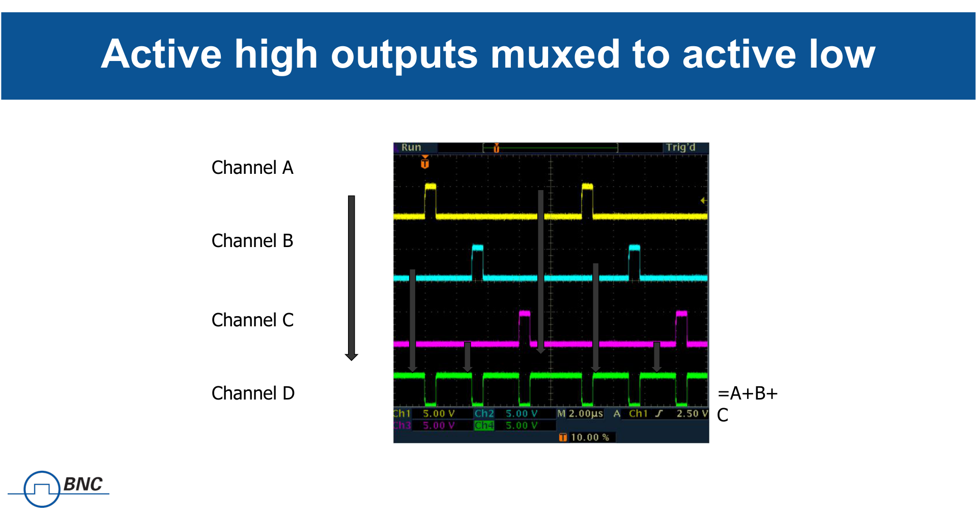
Beyond raw timing, the 577 is built for synchronization. Any channel can be OR'd to any output, gating can be applied per channel or across the system, and burst, nested-burst, and duty-cycle modes cover repetitive sequencing. A field-programmable FPGA keeps the feature set current, and 16 memory locations store full instrument configurations.
2Key Features
- Four or eight independent output channels
- 250 ps resolution on delay and pulse width
- Delay range 0 ns to 1000 s, pulse width 10 ns to 1000 s
- Repetition rate 0.001 Hz to 20 MHz
- Accuracy of 1 ns + 0.0001 times the setpoint
- Channel-to-channel jitter below 50 ps RMS
- Burst, nested-burst, and duty-cycle modes
- Channel multiplexing: OR any channel to any output
- USB and RS-232 standard; optional Ethernet and GPIB
- External clock sync, 10 MHz to 100 MHz
- Field-programmable FPGA and 16 memory locations
3Channels & Timing Architecture
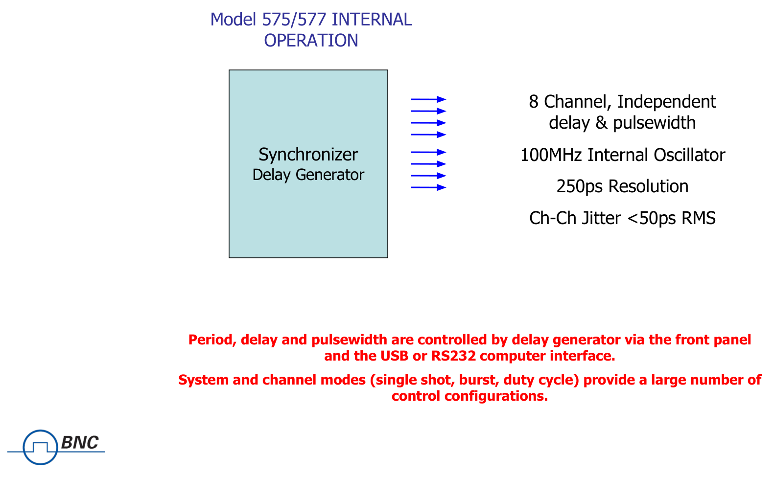
The Model 577 ships as a four-channel (577-4C) or eight-channel (577-8C) instrument. A single internal rate generator sets the system period (T0), and each channel runs its own delay, width, and output mode against that time base. Because any or all channels can be OR'd to any or all output BNCs, a single pulse can be steered to several outputs, or several channels can be combined onto one.
The time base is a 200 MHz low-jitter PLL driven from a 50 MHz, 50 ppm crystal oscillator, with selectable external clock reference from 10 MHz to 100 MHz. Negative delay, individual per-channel rates, and per-channel gating give the instrument the flexibility to act as the timing backbone of a multi-instrument setup.

4Specifications
Internal Rate Generator
| Parameter | Value |
|---|---|
| Rate (T0 period) | 0.001 Hz to 20.000 MHz (1000 s to 50 ns) |
| Resolution | 5 ns |
| Accuracy | 5 ns + (0.0001 x period) |
| T0 period jitter | < 50 ps RMS |
| Time base | 200 MHz low-jitter PLL |
| Oscillator | 50 MHz, 50 ppm crystal |
| System output modes | Single, normal, burst, duty cycle, external gate/trigger |
| Burst mode | 1 to 10,000,000 pulses |
Timing Generator
| Parameter | Value |
|---|---|
| Pulse width range | 10 ns to 1000 s |
| Width accuracy | 1 ns + 0.0001 x width setting |
| Width resolution | 250 ps |
| Pulse delay range | 0 to 1000 s |
| Delay accuracy | 1 ns + 0.0001 x delay setting |
| Delay resolution | 250 ps |
| Jitter (channel to channel) | < 50 ps RMS |
| Output multiplexer | Any/all channels may be OR'd to any/all outputs |
| Channel output modes | Single, normal, burst, duty cycle |
Standard Output Module (AT20)
| Parameter | TTL/CMOS Mode | Adjustable Mode |
|---|---|---|
| Output / source impedance | High impedance | — |
| Output level | 4.0 V typ into 1 kΩ | 2 V to 20 VDC into 1 kΩ or 1 V to 10 VDC into 50 Ω |
| Rise time (10% to 90%) | < 3 ns (1.5 ns typ) | 15 ns typ @ 20 V into Hi-Z (25 ns typ @ 10 V into 50 Ω) |
| Jitter | < 50 ps RMS channel to channel | — |
| Amplitude resolution | — | 10 mV |
| Current | — | 200 mA typ, 400 mA (short pulses) |
| Slew rate | — | 0.1 V/ns |
Optional 45 V Output Module (AT45)
| Parameter | Value |
|---|---|
| Amplitude | 4 V to 45 V |
| Resolution | 20 mV |
| Accuracy | ±1.5% |
| Rise time (10% to 90%) | < 2 ns into 50 Ω typ / < 9 ns into Hi-Z typ |
| Frequency (internal and external) | DC to 100 kHz |
| Max current | 35 mA (Hi-Z @ 10 ms width) / 900 mA (50 Ω @ 10 ms width) |
| Note | Maximum of four AT45 channels per unit |
Physical and Environmental
| Parameter | Value |
|---|---|
| Dimensions | 10.5 x 8.25 x 5.5 in [267 x 210 x 140 mm] |
| Weight | 8 lbs [3.6 kg] |
| Power | 100 to 240 VAC, 50/60 Hz, < 3 A |
| Operating temperature | 32 to 104 °F [0 to 40 °C] |
| Memory storage | 16 memory locations |
| External clock in/out | 10 MHz to 100 MHz, user selectable |
| Warranty | Full 3-year warranty with lifetime no-cost firmware upgrades |
5Triggering & I/O
The standard electrical input module (IA15) handles trigger and gate functions. The trigger input generates individual pulses, starts a burst, or starts a continuous stream; the gate input applies pulse inhibit or output inhibit, with active-high or active-low polarity. An optional dual-trigger input (DT15) adds a second input.
| Parameter | Trigger Input (IA15) |
|---|---|
| Rate | DC to 1/(200 ns + longest active pulse), max 5 MHz |
| Slope | Rising or falling |
| Threshold | 200 mV to 15 VDC |
| Maximum input | 60 V peak |
| Resolution | 10 mV |
| Trigger accuracy | ±3% of threshold voltage |
| Impedance | 1.2 kΩ |
| Trigger jitter | < 800 ps RMS |
| Insertion delay | < 110 ns |
| Minimum pulse width | 20 ns |
USB 1.0 and an RS-232 DE-9F connector are standard. Optical input and output modules (820 nm or 1300 nm, ST connector, up to 5 MBd over 1.5 km) are available for electrically isolated links.
6Options & Configurations
Channel output modules are selected per pair (A&B, C&D, E&F, G&H), so a single instrument can mix output types across its channels.
Channel output modules
- AT20: TTL (Hi-Z) / 2 to 20 V adjustable (Hi-Z), standard
- TZ50: TTL (50 Ω) / 2 to 20 V adjustable (Hi-Z)
- AT35: TTL (Hi-Z) / 5 to 35 V adjustable (50 Ω)
- TZ35: TTL (50 Ω) / 5 to 35 V adjustable (50 Ω)
- AT45: 4 to 45 V adjustable (Hi-Z / 50 Ω)
- L82: 820 nm optical output; L130: 1300 nm optical output
Trigger / gate input and system options
- IA15 electrical 15 V adjustable threshold input, standard
- IL82 / IL130 optical input
- DT15 dual trigger input
- COM: add LAN and GPIB port
- US 115 V or EU 230 V power cord
- P/N6923 single rack mount; P/N6978 dual rack mount
7Applications
- Laser systems
- Research applications
- Synchronization across multiple instruments
- Test setups
- Particle image velocimetry (PIV)
8Ordering / In the Box
Specify channel count and the output module for each channel pair when ordering, along with any input, communication, and rack-mount options. The instrument ships with power cord and a calibration certificate, and carries a full 3-year warranty with lifetime no-cost firmware upgrades.
| Item | Detail |
|---|---|
| 577-4C | Four independent output channels |
| 577-8C | Eight independent output channels |
To configure or quote, contact Berkeley Nucleonics at info@berkeleynucleonics.com or 800-234-7858.