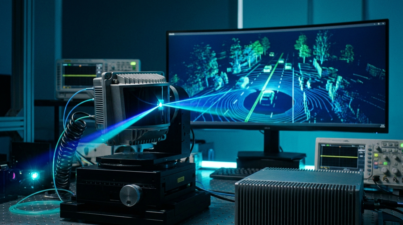
LiDAR Testing
LiDAR development lives and dies on timing. A sensor measures distance by counting the picoseconds between an emitted laser pulse and the reflection that comes back, so the bench that validates it has to produce those reflections with the same fidelity the real world would. Scenario emulation means generating the full set of return pulses a sensor would see in a scene: near and far targets, faint and bright returns, multiple objects layered in a single field of view, all placed in time exactly where the physics would put them. The pulsed-laser-diode side of the problem is the mirror image, where the test bench has to drive the emitter itself and shape the optical pulse the sensor sends out.
Both tasks share the same two ingredients. The waveform has to be long, because a realistic scenario unfolds over a wide time window and carries many distinct pulses, and the timing has to be exact, because a sensor that resolves centimeters is reading single-digit picoseconds. When a LiDAR unit uses several detector channels or several emitters, the bench has to feed all of them at once and keep them locked to each other.
The challenge
Traditional arbitrary waveform generators run into two walls when they try to emulate a full LiDAR scene. The first is memory depth. A long scenario with many returns spread across a wide window needs a deep waveform record, and generators that top out around 1 to 2 Gpts per channel force the test engineer to shorten the scene, drop targets, or stitch shorter segments together, none of which reflect how the sensor will behave in the field.
The second wall is jitter. The moment a bench runs many channels together, small timing errors accumulate. Channel-to-channel skew drifts, trigger jitter relative to the system clock creeps up, and the placement of each emulated reflection blurs. For a sensor whose entire job is precise ranging, that blur is the difference between a valid measurement and a meaningless one. The result is that realistic, long-duration, multi-channel scenarios become impractical on instruments that cannot hold both depth and timing at the same time.
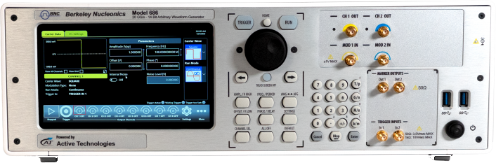
How the Model 686 solves it
The Berkeley Nucleonics Model 686 is built for exactly this combination of long records and tight timing. It addresses memory depth directly with up to 9 Gpts per channel, which is enough to store an extended LiDAR scenario in a single contiguous record rather than splicing fragments. A full scene of layered returns, across a wide time window, fits without compromise.
Timing is where the instrument earns its place on a LiDAR bench. Trigger jitter holds below 2 ps relative to an external master clock, so every scenario fires against the system reference with picosecond consistency. When a bench needs more channels than a single unit provides, separate Model 686 units synchronize to better than 100 fs, which lets a multi-emitter or multi-detector setup behave as one coherent system rather than a loose collection of generators. Within that timing budget, 50 ps timing resolution places each emulated reflected pulse precisely where the scene calls for it, so near and far targets land at their true ranges.
The output stage is matched to the application as well. The Model 686 delivers 5 Vpp into 50 ohm, enough to drive many pulsed-laser-diode test fixtures directly, without an external amplifier in the path adding its own delay and distortion. When a fixture needs more current than a 50 ohm AWG output can supply, the Model 686 pairs with a Berkeley Nucleonics high-voltage pulse generator that produces square-wave outputs up to 50 V into 1 A, giving the bench the drive level that high-power laser diodes require while keeping the timing under AWG control.
Recommended configuration
For scenario emulation, configure a single Model 686 with full memory depth so the longest planned scene fits in one record, and clock it from the bench master so the sub-2 ps trigger jitter is referenced to the same clock the sensor uses. Use the 50 ps resolution to lay out the target returns and the 5 Vpp output to drive the detector test fixture directly.
For a multi-channel LiDAR system, add Model 686 units and synchronize them to the sub-100 fs spec so emitters and detectors share one timebase. Where the fixture drives high-power laser diodes, add a Berkeley Nucleonics high-voltage pulse generator for the 50 V / 1 A square-wave drive and let the Model 686 keep the timing. Build each scenario once in deep memory, reference every channel to the master clock, and the bench will reproduce the same scene shot after shot. Confirm channel count, memory option, and output configuration against the current published Model 686 datasheet before ordering.
Talk to an application engineer
Berkeley Nucleonics works with OEM sensor labs, defense electro-optical and infrared test groups, and LiDAR hardware teams to match the Model 686 and its pulse-generator pairing to a specific bench. Call 800-234-7858 or email info@berkeleynucleonics.com.
For a quick question, chat with an engineer at berkeleynucleonics.com.