A 2 or 4 channel, 16-bit arbitrary waveform generator built for the bench and the automated test rack. The Model 670C samples at 600 MS/s, reaches 318 MHz of bandwidth, and runs in both a Simple AFG mode and a True ARB mode, with an optional 8 digital channels for full mixed-signal generation.
Model 670C · Document rev. A · Specifications subject to verification against the published Berkeley Nucleonics datasheet
1Overview
The Berkeley Nucleonics Model 670C is a cost-effective, high-performance arbitrary waveform generator that serves as both an arbitrary function generator (AFG) and a true arbitrary waveform generator (AWG) with advanced sequencer functionality. It ships in 2 or 4 analog channel configurations, samples at 600 MS/s (1.2 GS/s with x2 interpolation), and holds true 16-bit vertical resolution across every output.
With up to 318 MHz of bandwidth, an output range to 12 Vp-p, and up to 512 Msample of waveform memory per channel, the 670C suits demanding signal scenarios in automotive, IoT, medical, and research work. The optional 8 digital channels combine with the analog outputs to make the unit a full-featured mixed-signal generator, producing 2 or 4 analog signals fully synchronized with 8 digital lines on LVTTL or LVDS standards.
Operation runs through the Simple Rider user interface, a touch-driven AWG and AFG environment built for fast setup at the bench and clean integration into automated test. Two operating modes cover the full range of work: an AFG mode driven by direct digital synthesis for standard function-generator tasks, and a True ARB mode running a variable sampling clock for point-by-point arbitrary playback and sequencing.
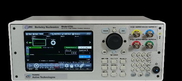
Model 670C front panel: 7-inch capacitive touch display, navigation wheel, and front-panel BNC channel outputs (CH1 through CH4), Trigger In, and Run controls.
2Key Features
2 or 4 analog channels. Single-ended, DC-coupled outputs on front-panel BNC connectors, with a marker output for synchronization.
600 MS/s sampling. 1 S/s to 600 MS/s, extending to 1.2 GS/s with x2 interpolation, at 16 Hz resolution and 2.0 ppm accuracy.
16-bit vertical resolution. Full 16-bit resolution in both AFG and True ARB modes for clean, low-distortion output.
Up to 318 MHz bandwidth. Up to 180 MHz sine output bandwidth in AFG mode, with greater than 200 MHz additive-noise bandwidth available.
Up to 12 Vp-p into 50 ohm. 0 to 6 Vp-p standard, 12 Vp-p with the high-voltage option or the 670C-4C-LF.
Up to 512 Msample memory per channel. Deep waveform memory for long records and complex sequences.
8 digital channels, optional. Synchronous with analog generation on LVDS, with LVTTL conversion available through an adapter probe.
Simple Rider UI. A touch-oriented interface designed for AWG and AFG users, running on a 7-inch capacitive touch display.
AFG mode runs in direct digital synthesis, driving standard function-generator waveforms on single-ended outputs through front-panel BNC connectors. Output impedance is programmable at 50 ohm or 0 ohm.
Parameter
Specification
Operating mode
DDS mode
Standard waveforms
Sine, Square, Pulse, Ramp, and more (Noise, DC, Sin(x)/x, Gaussian, Lorentz, Exponential Rise, Exponential Decay, Haversine)
Run modes
Continuous, modulation, sweep, burst
Arbitrary waveform vertical resolution
16-bit
Arbitrary waveform length
16,384 points
Internal trigger timer range
13.4 ns to 100 s
Internal trigger timer resolution
104 ps
Internal trigger timer accuracy
±(0.1% setting + 5 ps)
Frequency Accuracy & Resolution
Parameter
Specification
Frequency resolution (Sine, Square, Pulse, Arbitrary, Sin(x)/x)
1 µHz or 15 digits
Frequency resolution (Gaussian, Lorentz, Exponential Rise/Decay, Haversine)
1 µHz or 14 digits
Frequency accuracy (non-ARB)
±2.0 x 10⁻⁶ of setting
Frequency accuracy (ARB)
±2.0 x 10⁻⁶ of setting ±1 µHz
6Standard Waveforms
Sine Waves
Parameter
670C
670C-4C-LF
Frequency range (50 ohm into 50 ohm)
1 µHz to ≤150 MHz: 6 Vp-p; >150 MHz to ≤180 MHz: 5 Vp-p
HV option: 1 µHz to ≤50 MHz: 12 Vp-p; >50 MHz to ≤60 MHz: 10 Vp-p; >60 MHz to ≤100 MHz: 8 Vp-p; >100 MHz to ≤150 MHz: 6 Vp-p; >150 MHz to ≤180 MHz: 5 Vp-p
1 µHz to ≤50 MHz: 12 Vp-p; >50 MHz to ≤60 MHz: 10 Vp-p; >60 MHz to ≤100 MHz: 8 Vp-p
Maximum frequency
180 MHz
100 MHz
Flatness (1 Vp-p, relative to 1 kHz)
DC to 180 MHz: ±0.5 dB
DC to 100 MHz: ±0.5 dB
Harmonic distortion (1 Vp-p)
1 µHz to ≤20 kHz: <-75 dBc; >20 kHz to ≤1 MHz: <-70 dBc; >1 MHz to ≤10 MHz: <-65 dBc; >10 MHz to ≤50 MHz: <-55 dBc; >50 MHz to ≤120 MHz: <-45 dBc; >120 MHz to ≤180 MHz: <-40 dBc
1 µHz to ≤20 kHz: <-75 dBc; >20 kHz to ≤1 MHz: <-70 dBc; >1 MHz to ≤10 MHz: <-65 dBc; >10 MHz to ≤50 MHz: <-55 dBc; >50 MHz to ≤100 MHz: <-45 dBc
Total harmonic distortion (1 Vp-p)
10 Hz to 20 kHz: <0.04%
Spurious (1 Vp-p, excluding fSa-fOut, fSa-2*fOut)
1 µHz to ≤10 MHz: <-80 dBc; >10 MHz to ≤180 MHz: <-80 dBc + 6 dBc/octave
1 µHz to ≤10 MHz: <-80 dBc; >10 MHz to ≤100 MHz: <-80 dBc + 6 dBc/octave
Phase noise (1 Vp-p, 10 kHz offset)
10 MHz: <-127 dBc/Hz typ; 100 MHz: <-115 dBc/Hz typ
Square Waves
Parameter
670C
670C-4C-LF
Frequency range
1 µHz to 80 MHz: 6 Vp-p
HV option: 1 µHz to ≤30 MHz: 12 Vp-p; >30 MHz to ≤50 MHz: 11 Vp-p; >50 MHz to ≤70 MHz: 10 Vp-p; >70 MHz to ≤80 MHz: 9 Vp-p
1 µHz to ≤30 MHz: 12 Vp-p; >30 MHz to ≤50 MHz: 11 Vp-p
Rise/fall time
4 ns
5 ns
Overshoot (1 Vp-p)
<1%
<1%
Jitter (rms)
<2 ps
<2 ps
Pulse Waves
Parameter
670C
670C-4C-LF
Frequency range
1 µHz to 80 MHz: 6 Vp-p
HV option: 1 µHz to ≤3 MHz: 12 Vp-p; >3 MHz to ≤10 MHz: 11 Vp-p; >10 MHz to ≤70 MHz: 10 Vp-p; >70 MHz to ≤80 MHz: 9 Vp-p
1 µHz to ≤3 MHz: 12 Vp-p; >3 MHz to ≤10 MHz: 11 Vp-p; >10 MHz to ≤50 MHz: 10 Vp-p
Leading/trailing edge transition time
4 ns to 1000 s
5 ns to 1000 s
Pulse width
5 ns to (Period - 5 ns)
7 ns to (Period - 7 ns)
Pulse width resolution
20 ps or 15 digits
Transition time resolution
2 ps or 15 digits
Pulse duty
0% to 100%, 14 digits (pulse-width limitations apply)
Overshoot (1 Vp-p)
<1%
Jitter (rms, rise and fall time ≥4 ns)
<2 ps
Double Pulse Waves
Parameter
670C
670C-4C-LF
Frequency range
1 µHz to ≤3 MHz: 12 Vp-p; >3 MHz to ≤50 MHz: 6 Vp-p (Vp-p = |Vp-p1| + |Vp-p2|)
HV option: 1 µHz to ≤3 MHz: 24 Vp-p; >3 MHz to ≤10 MHz: 11 Vp-p; >10 MHz to ≤50 MHz: 10 Vp-p
1 µHz to ≤3 MHz: 24 Vp-p; >3 MHz to ≤10 MHz: 11 Vp-p; >10 MHz to ≤50 MHz: 10 Vp-p (Vp-p = |Vp-p1| + |Vp-p2|)
Other pulse parameters
Same as pulse waves
Ramp & Other Waves
Parameter
Specification
Ramp frequency range
1 µHz to 5 MHz
Ramp linearity (<10 kHz, 1 Vp-p, 100%)
≤0.1%
Ramp symmetry
0% to 100%
Exponential Rise / Exponential Decay frequency range
1 µHz to 5 MHz
Sin(x)/x, Gaussian, Lorentz, Haversine frequency range
1 µHz to 10 MHz
Additive noise bandwidth (-3 dB)
>200 MHz (670C); >100 MHz (670C-4C-LF)
Additive noise level
0 V to 6 V - |carrier max value [Vpk]|
Additive noise resolution
1 mV
Arbitrary (AFG Mode)
Parameter
670C
670C-4C-LF
Number of samples
2 to 16,384
Jitter (rms)
<2 ps
Frequency range
1 µHz to ≤80 MHz
1 µHz to ≤50 MHz
Analog bandwidth (-3 dB)
87.5 MHz
70 MHz
Rise/fall time
4 ns
5 ns
7Modulation
The 670C supports a full modulation suite in AFG mode. Across AM, FM, PM, FSK, PSK, and PWM, the carrier set covers all standard waveforms except where noted, plus ARB. The modulation source is internal, and internal modulating waveforms are Sine, Square, Ramp, Noise, and ARB (Square only for FSK and PSK).
Modulation
Carrier waveforms
Key parameters
Amplitude Modulation (AM)
Standard (except Pulse, DC, Noise), ARB
Modulating frequency 500 µHz to 48 MHz; depth 0.00% to 120.00%
Frequency Modulation (FM)
Standard (except Pulse, DC, Noise), ARB
Modulating frequency 500 µHz to 48 MHz; peak deviation DC to 180 MHz (670C), DC to 100 MHz (670C-4C-LF)
Phase Modulation (PM)
Standard (except Pulse, DC, Noise), ARB
Modulating frequency 500 µHz to 48 MHz; phase deviation 0° to 360°
Frequency Shift Keying (FSK)
Standard (except Pulse, DC, Noise), ARB
Modulating waveform Square; key rate 500 µHz to 48 MHz; 2 keys; hop frequency 1 µHz to 180 MHz (670C), 1 µHz to 100 MHz (670C-4C-LF)
Phase Shift Keying (PSK)
Standard (except Pulse, DC, Noise), ARB
Modulating waveform Square; key rate 500 µHz to 48 MHz; hop phase 0° to +360°; 2 keys
Pulse Width Modulation (PWM)
Pulse
Modulating frequency 500 µHz to 48 MHz; deviation 0% to 50% of pulse period
8Sweep & Burst
Sweep parameter
Specification
Type
Linear, Logarithmic, Staircase, and user defined
Waveforms
Standard waveforms (except Pulse, DC, Noise), ARB
Sweep time
40 ns to 2000 s
Hold/return times
0 to (2000 s - 40 ns)
Sweep/hold/return time resolution
20 ns or 12 digits
Total sweep time accuracy
≤0.4%
Trigger source
Internal / External / Manual
Start/stop frequency range
670C: Sine 1 µHz to 180 MHz, Square 1 µHz to 80 MHz. 670C-4C-LF: Sine 1 µHz to 100 MHz, Square 1 µHz to 50 MHz
Burst parameter
Specification
Waveforms
Standard waveforms (except DC and Noise), ARB
Type
Triggered or Gated
Burst count
1 to 4,294,967,295 cycles or Infinite
9True ARB Mode
True ARB mode runs a variable sampling clock for point-by-point arbitrary playback with advanced sequencing. Outputs are single-ended, DC coupled, on front-panel BNC connectors at 50 ohm or 0 ohm impedance.
16 to 2M samples per channel (up to 512M samples optional)
16 to 2M samples per channel (up to 128M samples optional)
Waveform granularity
1 if entry length >384 samples; 8 if entry length ≥16 and ≤384 samples
Sequence length
1 to 16,384
Sequence repeat counter
1 to 4,294,967,295 or infinite
Timer range
23.52 ns to 7 s
Timer resolution
±1 sampling clock period
Channel Skew & Signal Quality
Parameter
670C
670C-4C-LF
Channel-to-channel skew range
0 to 6.59 µs (depending on internal sampling rate)
Skew resolution
CH1/2 to CH3/4: ≤5 ps; CH1/3 to CH2/4: 1 DAC sampling period
Skew accuracy
±(1% of setting + 20 ps)
Initial skew
<200 ps
Calculated bandwidth (0.35 / rise or fall time)
≥160 MHz
≥100 MHz
Harmonic distortion (sine 32 pts, 1 Vp-p)
<-62 dBc (@ 600 MS/s, 18.75 MHz)
Spurious (sine 32 pts, 1 Vp-p)
<-80 dBc (@ 600 MS/s, 18.75 MHz)
SFDR (sine 32 pts, 1 Vp-p, including harmonics)
<-62 dBc (@ 600 MS/s, 18.75 MHz)
Rise/fall time (1 Vp-p single-ended, 10% to 90%)
≤2.2 ns
≤3.5 ns
Overshoot (1 Vp-p single-ended)
<2%
Timing & Clock
Parameter
Specification
Sampling rate range
1 S/s to 600 MS/s (1 S/s to 1.2 GS/s with x2 interpolation)
Sampling rate resolution
16 Hz
Sampling rate accuracy
±2.0 ppm
Random jitter on clock pattern (rms)
<2 ps
10Digital Outputs
The optional 8-channel digital output runs synchronously with analog generation, supporting full mixed-signal scenarios.
Parameter
Specification
Connector
Mini-SAS HD connector on rear panel (non-standard pin-out)
Number of connectors
1
Number of outputs
8 bits
Output impedance
100 ohm differential
Output type
LVDS
Rise/fall time (10% to 90%)
<1 ns
Jitter (rms)
20 ps
Maximum update rate
600 Mbps
Memory depth
2 Msamples per digital channel (up to 512 Msamples optional)
LVDS to LVTTL Converter Probe (Optional AT-DTTL8)
Parameter
Specification
Output connector
20 position 2.54 mm 2-row IDC header
Output type
LVTTL
Output impedance
50 ohm nominal
Output voltage
0.8 V to 3.8 V programmable
Maximum update rate
125 Mbps @ 0.8 V and 400 Mbps @ 3.6 V
Dimensions
W 52 mm, H 22 mm, D 76 mm
Cable length / type
1 meter, proprietary standard
11Auxiliary I/O
Marker Output
Parameter
670C-2C
670C-4C-LF, 670C-4C
Connector type
BNC on front panel
BNC on rear panel
Number of connectors
1
Output impedance
50 ohm
Output amplitude (into 50 ohm)
1 V to 2.5 V
Resolution
10 mV
Accuracy
±(2% setting + 10 mV)
Rise/fall time (10% to 90%, 2.5 Vp-p)
<700 ps
Jitter (rms)
20 ps
Marker out to analog channel skew range
True ARB mode: 0 to 3 µs; AFG mode: 0 to 14 s (Continuous), 0 to 3 µs (Triggered)
Skew resolution
True ARB mode: 78 ps; AFG mode: 39 ps
Skew accuracy
±(1% of setting + 140 ps)
Initial skew
<1 ns
Trigger / Gate Input
Parameter
670C-2C
670C-4C-LF, 670C-4C
Connector
BNC on front panel
BNC on rear panel
Input impedance
50 ohm / 1 kohm programmable
Slope/polarity
Positive, negative, or both
Input damage level
<-15 V or >+15 V
Threshold control level
-10 V to 10 V
Threshold resolution
10 mV
Threshold control accuracy
±(10% of |setting| + 0.2 V)
Input voltage swing
0.5 Vp-p minimum
Minimum pulse width (1 Vp-p)
3 ns
Initial trigger/gate delay to analog output
AFG mode: <400 ns (<460 ns in triggered sweep mode); True ARB mode: <131*DAC sampling period + 22.5 ns (<143*DAC sampling period + 22.5 ns with 2x interpolation)
Trigger in to output jitter
AFG mode: <45 ps; True ARB mode: 0.29*DAC sampling period
Maximum frequency
AFG mode: 55 MTps on Rising/Falling edge, 80 MTps on Both edges; True ARB mode: 42.5 MTps on Rising/Falling edge, 42.5 MTps on Both edges (MTps = Mega Transitions per second)
12Reference Clock
Reference clock input
Specification
Connector type
SMA on rear panel
Input impedance
50 ohm, AC coupled
Input voltage range
-4 dBm to 11 dBm sine or square wave (rise time T10-90 <1 ns, duty cycle 40% to 60%)
Damage level
+14 dBm
Frequency range
5 MHz to 100 MHz
Reference clock output
Specification
Connector type
SMA on rear panel
Output impedance
50 ohm, AC coupled
Frequency
10 MHz
Accuracy
±2.0 x 10⁻⁶
Aging
±1.0 x 10⁻⁶/year
Amplitude
1.65 V
Jitter (rms)
<20 ps
13System & Environment
Power
Parameter
Specification
Source voltage & frequency
100 to 240 VAC ±10% @ 45 Hz to 66 Hz
Maximum power consumption
100 W
Environmental
Parameter
Specification
Temperature (operating)
+41 F to 104 F (+5 C to +40 C)
Temperature (non-operating)
-4 F to 140 F (-20 C to +60 C)
Humidity (operating)
5% to 80% RH, maximum wet bulb 29 C at or below +40 C (upper limit derates to 20.6% RH at +40 C). Non-condensing.
Humidity (non-operating)
5% to 95% RH, maximum wet bulb 40 C at or below +60 C (upper limit derates to 29.8% RH at +60 C). Non-condensing.
Altitude (operating)
9,842 ft (3,000 m) maximum at or below 25 C
Altitude (non-operating)
39,370 ft (12,000 m) maximum
EMC & Safety
Parameter
Specification
Compliance
CE compliant
Safety
EN 61010-1
Main standard
EN 61326-1:2013 (Electrical equipment for measurement, control and laboratory use, EMC requirements, Part 1: General requirements)
Immunity
EN 61326-1:2013
System Specifications
Parameter
670C-2C
670C-4C, 670C-4C-LF
Display
7-inch, 1024 x 600, capacitive touch LCD
Operating system
Windows 10
External dimensions
W 14.25 in x H 5.63 in x D 10.16 in (W 362 mm x H 143 mm x D 258 mm); 3U 10-inch rackmount
Weight
13.78 lb (6.25 kg)
Front-panel connectors
CH1, CH2 OUTPUT (BNC); MARKER OUT (BNC); TRIGGER IN (BNC)
CH1, CH2 OUTPUT (BNC); CH3, CH4 OUTPUT (BNC)
Rear-panel connectors
REF CLK IN (SMA); REF CLK OUT (SMA); External Monitor ports; DIGITAL POD A[7..0]; 1 USB 2.0 port or more; Ethernet (10/100/1000BaseT, RJ45); 2 PS/2 keyboard and mouse ports
REF CLK IN (SMA); REF CLK OUT (SMA); MARKER OUT (BNC); TRIGGER IN (BNC); External Monitor ports; DIGITAL POD A[7..0]; 1 USB 2.0 port or more; Ethernet (10/100/1000BaseT, RJ45); 2 PS/2 keyboard and mouse ports
Hard disk
240 GB SSD or better
Processor
Intel Celeron J1900, 2 GHz (or better)
Processor memory
4 GB or better
14Models & Options
Available Models
Item
Description
670C-2C-2M
2 ch 600 MS/s AWG, 2 Ms memory, 180 MHz AFG
670C-2C-64M
2 ch 600 MS/s AWG, 64 Ms memory, 180 MHz AFG
670C-2C-256M
2 ch 600 MS/s AWG, 256 Ms memory, 180 MHz AFG
670C-2C-512M
2 ch 600 MS/s AWG, 512 Ms memory, 180 MHz AFG
670C-4C-2M
4 ch 600 MS/s AWG, 2 Ms memory, 180 MHz AFG
670C-4C-64M
4 ch 600 MS/s AWG, 64 Ms memory, 180 MHz AFG
670C-4C-256M
4 ch 600 MS/s AWG, 256 Ms memory, 180 MHz AFG
670C-4C-512M
4 ch 600 MS/s AWG, 512 Ms memory, 180 MHz AFG
670C-4C-2M-LF
4 ch 600 MS/s AWG, 2 Ms memory, 100 MHz AFG
670C-4C-128M-LF
4 ch 600 MS/s AWG, 128 Ms memory, 100 MHz AFG
Options & Accessories
Item
Type
Description
670C-2C-HV
Option
High-voltage output (12 Vpp on 50 ohm)
670C-4C-HV
Option
High-voltage output (12 Vpp on 50 ohm)
8DIG
Option
8 channel digital license
AT-DTTL8
Accessory
LVDS to LVTTL digital adapter probe
AT-LVDS-SMA8
Accessory
LVDS to SMA digital adapter cable
RIDER-C-RACK
Accessory
Rackmount kit for Rider C series
GPIB / USB-TMC
Accessory
GPIB and USB-TMC ports for remote control
SSD-250
Accessory
Additional 250 GB solid state disk for RIDER series
SSD-500
Accessory
Additional 500 GB solid state disk for RIDER series
SSD-1000
Accessory
Additional 1 TB solid state disk for RIDER series
Configuration note. Memory depth, channel count, AFG bandwidth (180 MHz or 100 MHz LF), and the high-voltage and digital options are selected at order. Confirm the exact build against the published Berkeley Nucleonics datasheet before quoting.
15Applications
The Model 670C suits work that needs precise, repeatable signal generation across analog and mixed-signal domains:
Automotive. Sensor and bus emulation, signal injection, and waveform replay for component and system test.
IoT and Industry 4.0. Acting as a precise RF modulator and stimulus source for connected-device validation.
Aerospace and defense. Radar and pulse waveform synthesis, sequenced playback, and trigger-aligned test scenarios.
Semiconductors. Device characterization and mixed-signal stimulus with the optional 8 digital channels synchronized to analog generation.
16Software & Support
The Model 670C runs the Simple Rider user interface, a touch-driven AWG and AFG environment on the 7-inch capacitive display. For remote control and automation, the instrument supports Ethernet, USB, and optional GPIB or USB-TMC, and pairs with the Rider software development kit.
Request the full datasheet. This page summarizes published specifications. For the complete Model 670C datasheet, ordering details, and lead times, contact Berkeley Nucleonics (opens in a new window).