1Introduction
This manual is a reference designed to familiarize you with the Berkeley Nucleonics Corporation 588B series pulse generator and is arranged so that you can easily find the information you're looking for. Generally, each topic has its own section and no section assumes that you've read anything else in the manual.
Rack Mount Models
| Configuration | Model Number |
|---|---|
| 12 Channel Units | BNC588B-12C |
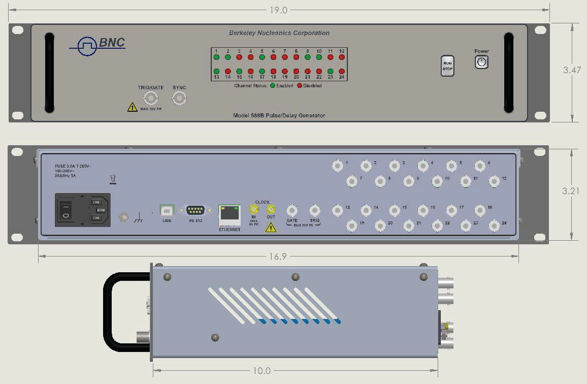
| 24 Channel Units | BNC588B-24C |
Technical Support
For questions or comments about operating the 588B our technical staff can be reached via one of the following methods:
- Phone – (415) 453-9955
- Fax – (415) 453-9956
- Internet – www.berkeleynucleonics.com
Warranty
In addition to a 30-day money back guarantee, the 588B has a two-year limited warranty from the date of delivery. This warranty covers defects in materials and workmanship. Berkeley Nucleonics Corporation will repair or replace any defective unit. Contact us for information on obtaining warranty service.
Package Contents
The box you receive should contain the following:
- 588B Pulse Generator
- AC Power Cord*
- User's Manual and GUI on USB
Contact Berkeley Nucleonics Corporation (415) 453-9955 if any parts are missing.
2Safety Issues
Normal use of test equipment presents a certain amount of danger due to electrical shock because it may be necessary for testing to be performed where voltage is exposed.
An electrical shock causing 10 milliamps of current to pass through the heart will stop most human heartbeats. Voltage as low as 35 VDC or 35 VRMS AC should be considered dangerous and hazardous, as it can produce a lethal current under certain conditions. Higher voltages pose an even greater threat because such voltage can easily produce a lethal current. Your normal work habits should include all accepted practices that will prevent contact with exposed high voltage and steer current away from your heart in case of accidental contact with a high voltage. You will significantly reduce the risk factor if you know and observe the following safety precautions:
- If possible, familiarize yourself with the equipment being tested and the location of its high-voltage points. However, remember that high voltage may appear at unexpected points in defective equipment.
- Do not expose high voltage needlessly. Remove housing and covers only when necessary. Turn off equipment while making test connections in high-voltage circuits. Discharge high-voltage capacitors after shutting down power.
- When testing AC powered equipment, remember that AC line voltage is usually present on power input circuits, such as the on-off switch, fuses, power transformer, etc.
- Use an insulated floor material or a large, insulated floor mat to stand on, and an insulated work surface on which to place equipment. Make certain such surfaces are not damp or wet.
- Use the time-proven "one hand in the pocket" technique while handling an instrument probe. Be particularly careful to avoid contact with metal objects that could provide a good ground return path.
- Never work alone. Someone should always be nearby to render aid if necessary. Training in CPR first aid is highly recommended.
3System Overview
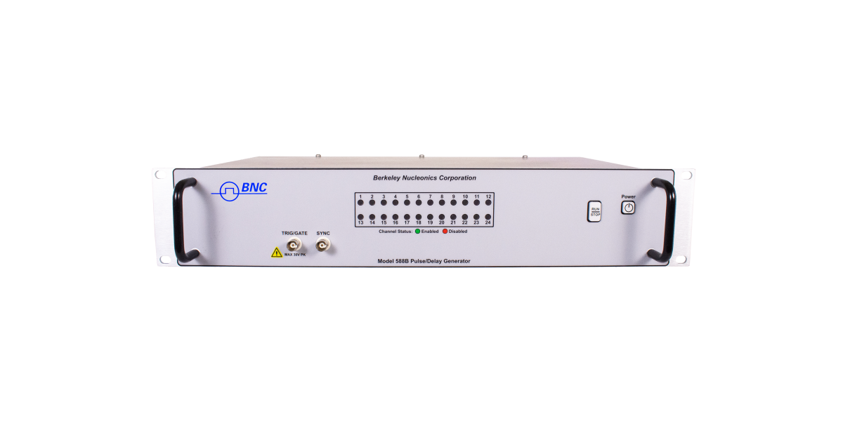
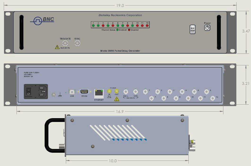
588B Front Panel
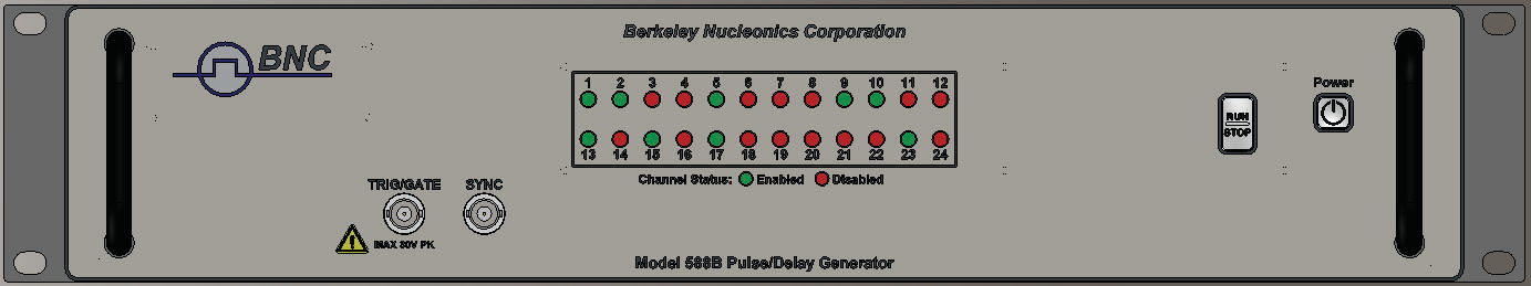
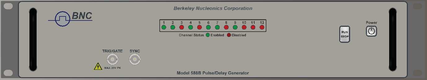
Front Panel Layout
An array of LEDs provides channel status, green indicates the channel is enabled, red indicates the channel is disabled. On power up all the LEDs will be green for 1 second and then red for 1 second to confirm operation. Error messages are indicated by blinking LEDs.
The power button and the Run button are on the right side of the front panel. On the left is a general-purpose Trigger / Gate input. The input range is 0.5v to 30v. In addition, a switch closure may be used, allowing the use of a foot switch or safety interlock.
588B Rear Panel
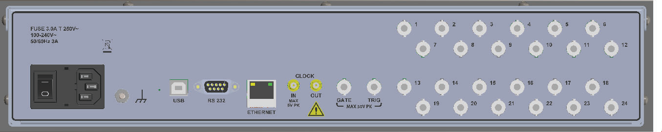
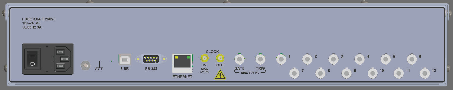
Rear Panel Layout
The channel outputs are available from an array of BNCs. There is a BNC trigger input and a BNC Gate input. The input range is 0.5v to 30v for both inputs. In addition, a switch closure may be used, allowing the use of a foot switch or safety interlock. A pair of SMA connectors provide for the input of a reference oscillator and the output of the internal system T0 pulse or a synthesized oscillator output. The unit provides three communication ports, RS232, USB & Ethernet. The power entry module provides a power on/off switch and accepts 100 to 240VAC at 50Hz or 60Hz.
4Pulse Concepts and Pulse Generator Operations
Counter Architecture Overview
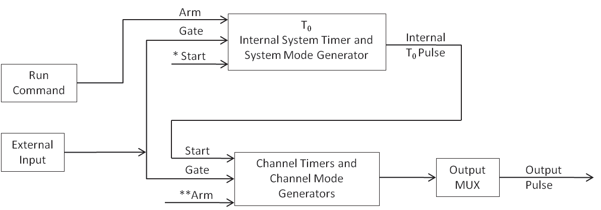
*Start source is:
- RUN button in Internal Modes
- External input in External Trigger modes
- *TRG command via Serial access
**Channels are armed by the RUN button. In single shot and burst modes channels may be rearmed by pressing the RUN button again.
System Timer Functions
The system timer generates the internal T0 pulse which is used as the Start pulse for the channel timers. The system timer functions as a non-retriggerable, multi-vibrator pulse generator. This means that once started, depending on the mode, the timer will produce pulses continuously. Before pulses can be generated, the timer must be armed and then receive a start pulse. Arming the counter is done by pressing the Run/Stop key or using the comm commands. With external trigger disabled, the Run/Stop key also generates the start command for the counter. With external trigger enabled, the external trigger provides the start pulse. In either case, once started, the counter operation is determined by the System Mode Generator. Standard modes include:
- Continuous – Once started T0 pulses are generated continuously.
- Single Shot – One T0 pulse is generated for each start command.
- Burst – 'n' T0 pulses are generated for each start command.
- Duty Cycle – Once started T0 pulses cycle on and off continuously.
The T0 pulse is distributed to all of the start inputs of the Channel Timers and Mode Generators.
Channel Timer Functions
The Channel Timer functions as a non-retriggerable, delayed, one shot pulse generator. This means that the timer will only generate one delayed pulse for every start pulse received. Once the channel timer has started counting, additional start pulses will be ignored until the pulse has been completed (non-retriggerable). The start pulse for each channel is provided by the internal T0 pulse generated by the internal system timer. Whether or not a pulse is generated for each T0 pulse is determined by the Channel Mode Generator. Standard modes include:
- Normal – A pulse is generated for each T0 pulse.
- Single Shot – One pulse is generated for the first T0 pulse, after which the output is inhibited.
- Burst – 'n' number of pulses are generated for the first T0 pulse, after which the output is inhibited.
- Duty Cycle – 'n' number of pulses are generated for each T0 pulse after which the output is inhibited for 'm' number of pulses. The cycle is then repeated for each subsequent T0 pulse.
Different modes may be selected for each output, allowing a wide variety of output combinations. Each output may also be independently disabled or gated (using the external gate input).
Digital Output Multiplexer
The outputs of each of the Channel Timers are routed to a set of multiplexers. This allows routing of a number (up to 5) Channel Timers to each of the output ports.
The mux value (0 to 31) is determined by the enabled bits: bit 0 = 1, bit 1 = 2, bit 2 = 4, bit 3 = 8, bit 4 = 16.
Command: :PULSe n:MUX 0 to 31 where 'n' is the channel number.
The following table lists the channel multiplexer bit assignments. The Bit 3 column (parameter = 8) routes channel 2 for all outputs; the Bit 4 column (parameter = 16) routes channel 12 or 24 depending on the system channel size.
| Output | Bit 3 (=8) | Bit 4 (=16) | Bit 2 (=4) | Bit 1 (=2) | Bit 0 (=1) |
|---|---|---|---|---|---|
| Bank A – 12 / 24 Channel Units | |||||
| Output Channel 1 | 12 | 2 | 5 | 3 | 1 |
| Output Channel 2 | 12 | 2 | 6 | 4 | 2 |
| Output Channel 3 | 12 | 2 | 1 | 5 | 3 |
| Output Channel 4 | 12 | 2 | 2 | 6 | 4 |
| Output Channel 5 | 12 | 2 | 3 | 7 | 5 |
| Output Channel 6 | 12 | 2 | 4 | 2 | 6 |
| Output Channel 7 | 12 | 2 | 11 | 9 | 7 |
| Output Channel 8 | 12 | 2 | 12 | 10 | 8 |
| Output Channel 9 | 12 | 2 | 7 | 11 | 9 |
| Output Channel 10 | 12 | 2 | 8 | 12 | 10 |
| Output Channel 11 | 12 | 2 | 9 | 13 | 11 |
| Output Channel 12 | 12 | 2 | 10 | 8 | 12 |
| 24 Channel Units | |||||
| Output Channel 13 | 12 | 24 | 17 | 15 | 13 |
| Output Channel 14 | 12 | 24 | 18 | 16 | 14 |
| Output Channel 15 | 12 | 24 | 13 | 17 | 15 |
| Output Channel 16 | 12 | 24 | 14 | 18 | 16 |
| Output Channel 17 | 12 | 24 | 15 | 13 | 17 |
| Output Channel 18 | 12 | 24 | 16 | 14 | 18 |
| Output Channel 19 | 12 | 24 | 23 | 21 | 19 |
| Output Channel 20 | 12 | 24 | 24 | 22 | 20 |
| Output Channel 21 | 12 | 24 | 19 | 23 | 21 |
| Output Channel 22 | 12 | 24 | 20 | 24 | 22 |
| Output Channel 23 | 12 | 24 | 21 | 19 | 23 |
| Output Channel 24 | 12 | 24 | 22 | 20 | 24 |
In the normal mode of operation bit 0 is the only bit enabled (bit pattern: 00001, command parameter 1), thus the output of the nth channel timer is routed to the nth output channel connector. Note that the channel routed to bit 3 (parameter = 8) is channel 2 for all outputs and the channel routed to bit 4 (parameter = 16), 12 or 24, depends on the system channel size. Using the MUX function with the channel modes allows a number of complex functions, such as double pulsing and modulating pulsewidths as shown in the following examples:
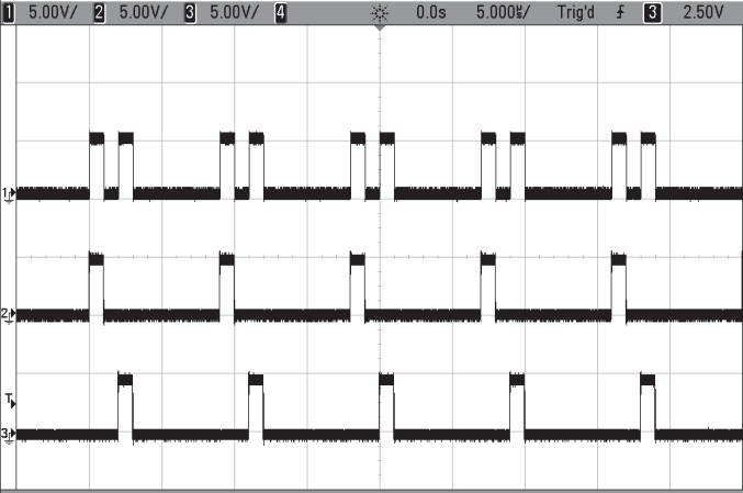
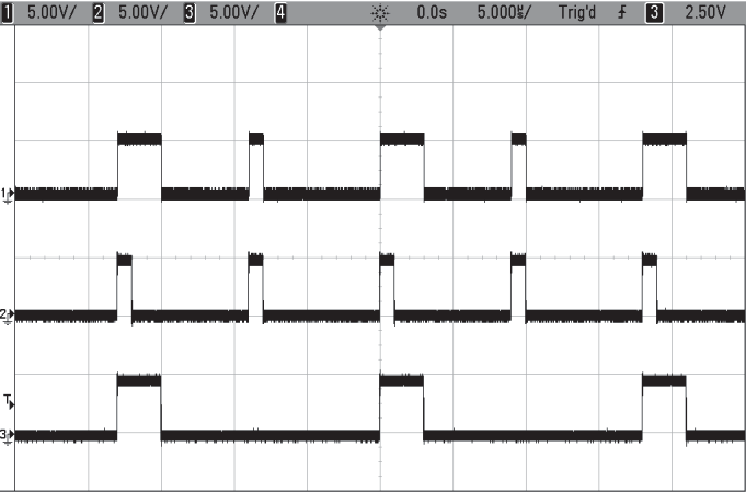
Ex. 1: Double Pulse
A double pulse waveform can be generated, as shown in the figure, by using the MUX function to combine two channels.
- Scope Ch 1: Channel 1 output after combining channel 1 and channel 3 (mux code: 3).
- Scope Ch 2: Channel 1 output before combining channel 3 (mux code: 1).
- Scope Ch 3: Channel 3 output delayed as necessary to generate the required second pulse (mux code: 1).
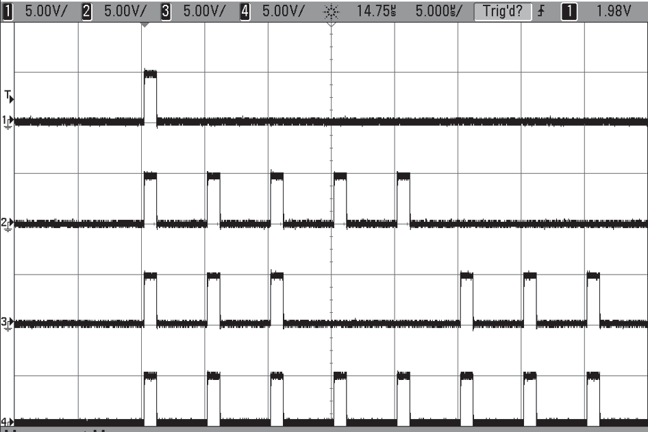
Ex. 2: Alternating Pulsewidth
An extended pulse can be generated every other pulse, as shown in the figure, by using the MUX function to combine two channels.
- Scope Ch 1: Channel 2 output after combining channel 2 and channel 4 (mux code: 3).
- Scope Ch 2: Channel 2 output before combining channel 4 (mux code: 1).
- Scope Ch 3: Channel 4 output extended as necessary to generate the required second pulse (mux code: 1). The channel is in duty cycle mode (1 on, 1 off) to generate the alternating pattern.
Channel Gate Function
The outputs of each of the Channels can be gated by one of two channel timers as defined below. In the gated mode, output of the gated channels only occurs when the gate is high (active high mode). The gate A timer (4) is common to all channels. The gate B timer (12 or 24) depends on the model, 12 or 24 channels, respectively. In the inhibit mode, output of the gated channels is inhibited when the gate is high (active low mode).
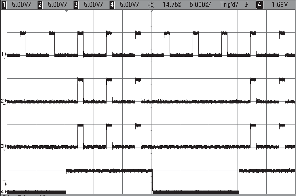
Gate A Mode
- Scope Ch 1: Ch 1 – Normal Mode
- Scope Ch 2: Ch 2 – Gate A (GATA) Enabled
- Scope Ch 3: Ch 3 – Gate A (GATA) Enabled
- Scope Ch 4: Ch 4 – Normal Mode (extended delay & width)
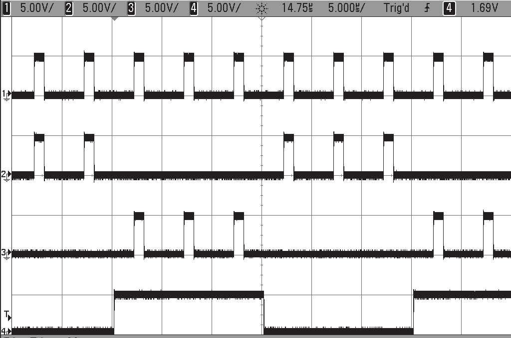
Gate B & Inhibit B Mode
- Scope Ch 1: Ch 1 – Normal Mode
- Scope Ch 2: Ch 2 – Inhibit B (INHB) Enabled
- Scope Ch 3: Ch 3 – Gate B (GATB) Enabled
- Scope Ch 4: Ch 12 – Normal Mode (extended delay & width)
Command: :PULSe n:CONTROL GATA|GATB|INHB
| Gate / Inhibit Function | GATE-A | GATE-B | INHIBIT-B |
|---|---|---|---|
| 12 Channel Units | 4 | 12 | 12 |
| 24 Channel Units | 4 | 24 | 24 |
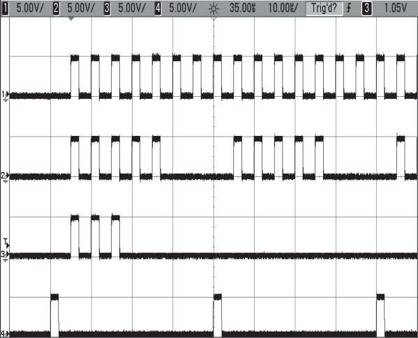
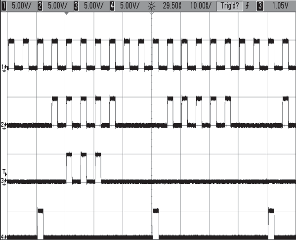
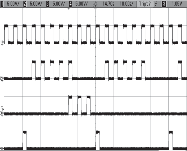
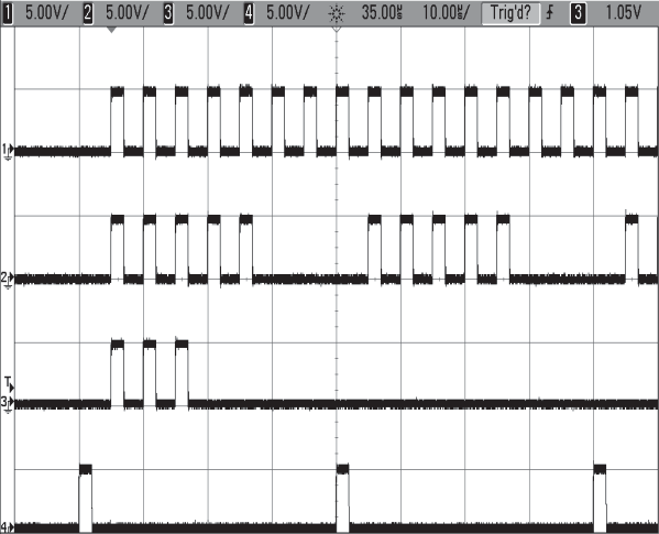
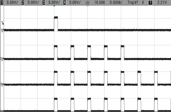
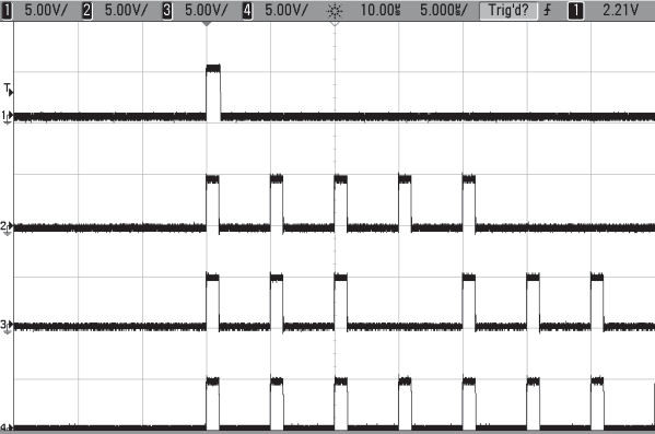
Channel Phase Locking
Normally when rearming a channel, the output will start on the next available T0 pulse. This leads to a random phase relationship with other channels that may be in duty cycle mode, as shown in column 1. The BNC588B channel sync feature can be used to lock the channel relative to the sync pulse, as shown in column 2. Note that when sync is enabled, the Ch3 burst is always locked to the start of Ch2 output.
- Column 1 – Sync Mode Disabled
- Column 2 – Sync Mode Enabled
- Scope Ch1 – channel 1 – normal mode, wait = 1
- Scope Ch2 – channel 2 – duty cycle mode (5 on, 3 off), wait = 1
- Scope Ch3 – channel 3 – burst mode (3 pulses), wait = 0
- Scope Ch4 – channel 6 – (sync pulse) duty cycle mode (1 on, 7 off), wait = 0
Command: :PULSe n:SYNC SYNA|SYNB|SYNT
| Channel Sync Function | SYNC-A | SYNC-B | SYNC-T (trigger sync) |
|---|---|---|---|
| 6 / 12 Channel Units | 6 | 12 | trigger sync |
| 24 Channel Units | 6 | 24 | trigger sync |
Operating the 588B
The 588B has a powerful set of functions providing a number of modes of operation. Both the system timer and the channel timer combine to provide the ability to generate complex waveforms. Configuring the system is done via the BNC GUI or using the computer interface command set. The available computer interfaces include a USB port, RS232 port and optional Ethernet port.
Quick Start – Normal Internal Rate Generator Operation
The 588B has a powerful set of functions providing a number of modes of operation for the internal or "System" rate generator (T0). Most of these functions can be ignored if a simple continuous stream of pulses is required. Starting from the default settings, which can be restored by recalling configuration 0, the following parameters need to be set:
| T0 Period | Set the Rate using either the supplied GUI or using the command set on one of the computer interfaces. The system mode should be in Continuous Mode. |
| Pulse Width and Delay | Set the required pulse width and delay using either the supplied GUI or using the command set on one of the computer interfaces. Enable or Disable the channel as required. The mode will be "normal". Repeat for each output channel. |
| Start | Press the Run/Stop key to start generating pulses. |
| Stop | Press the Run/Stop key a second time to stop generating pulses. |
Quick Start – Normal External Trigger Operation
To generate a single pulse for every external trigger event, based on the default configuration 0, the following parameters need to be set:
| System Mode | Set the System Mode using either the supplied GUI or using the command set on one of the computer interfaces. Select Single Shot mode. |
| Trigger | Set the Trigger using either the supplied GUI or using the command set on one of the computer interfaces. Select Trigger Enable. |
| Level | Set the Level parameter using either the supplied GUI or using the command set on one of the computer interfaces. Set the trigger threshold voltage to approximately 50% of the trigger signal amplitude. |
| Edge | Set the Edge parameter using either the supplied GUI or using the command set on one of the computer interfaces. Set the unit to trigger off the rising or falling edge as desired. |
| Pulse Width and Delay | Set the required pulse width and delay using either the supplied GUI or using the command set on one of the computer interfaces. Repeat for each output channel. |
| Start | Press the Run/Stop key to start generating pulses or use either the supplied GUI or use the command set on one of the computer interfaces. |
| Stop | Press the Run/Stop key a second time, or use either the supplied GUI or use the command set on one of the computer interfaces, to stop generating pulses. |
System Timer Overview
For internal operation, the 588B contains a timer and mode generator which generates an internal T0 clock that is used to trigger all the channel timers. System modes are controlled via the Mode menu.
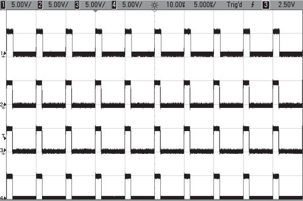
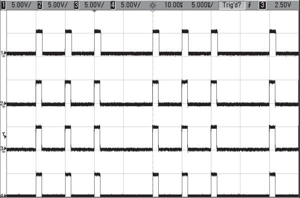
Using Continuous Mode
The Run/Stop button starts and stops a continuous pulse stream at the rate specified by the system Period parameter. This corresponds to the normal output mode for most pulse generators. To generate a continuous stream of pulses:
- System Mode: Continuous mode
- System Period: 10µs
Pressing the front panel Run/Stop key or entering the system State command will now generate a stream of pulses at a rate specified by the period parameter. Scope Ch 1–4: Channels 1 through 4 set to normal mode.
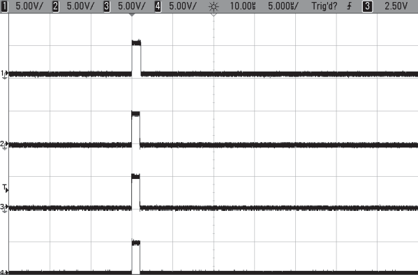
Using Single Shot Mode
To generate a single pulse with every press of the Run/Stop key or the State enable command:
- System Mode: Single Shot mode
Pressing the front panel Run/Stop key or entering the system State command will now generate one pulse. Scope Ch 1–4: Channels 1 through 4 set to normal mode.
Using System Burst Mode Function
The Run/Stop button generates a stream of 'N' T0 pulses, where the 'N' is specified by the Burst parameter. The rate is specified in the Rate menu. Pressing the Run/Stop button while the burst is in process will stop the output. After the burst has been completed, pressing the Run/Stop button will generate another burst. To generate a burst of pulses set:
- System Mode: Burst mode
- Burst Count: 5
- System Period: 10µs
Pressing the front panel Run/Stop key or entering the system State command will now generate a burst of the specified number of pulses. Scope Ch 1–4: Channels 1 through 4 set to normal mode.
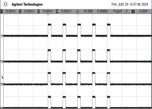
Using the System Duty Cycle Function
The Run/Stop button starts a continuous stream of T0 pulses, which oscillates on for 'N' pulses and off for 'M' pulses, where 'N' and 'M' are specified by the On/Off parameters respectively. The rate at which the pulses are generated is controlled in the Rate menu. To generate a stream of pulses which will oscillate on for 'N' pulses and off for 'M' pulses set:
- System Mode: Duty Cycle mode
- On Count: 3
- Off Count: 1
- System Period: 10µs
Pressing the front panel Run/Stop key or entering the system State command will now generate a continuous stream of pulses in bursts as defined by the on/off parameters. Scope Ch 1–4: Channels 1 through 4 set to normal mode.
Channel Timer Overview
The output of each channel is controlled by two timers to generate the pulse width and the delay timing. All channels are simultaneously triggered, depending on the system mode, by the internal T0 pulse, the external trigger, or a trigger provided by a CPU. A given channel may or may not generate a pulse depending on its own channel mode as described below.
Using Channel Normal Function
The Normal mode generates a continuous string of pulses once the Run/Stop key is pressed. To use channel normal mode set:
- System Mode: Continuous mode
- System Period: 10µs
- Set the Channel parameters:
- Enable the channel output
- Set the delay desired.
- Set the pulse width desired.
Pressing the front panel Run/Stop key or entering the system State command will now generate a stream of T0 pulses at a rate specified by the system period parameter. Scope Ch 1–4: Channels 1 through 4 set to normal mode.
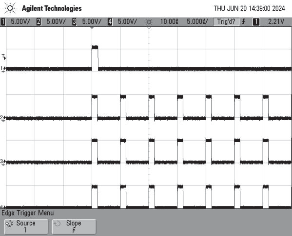
Using Channel Single Shot Function
The Single Shot mode generates a single pulse every time the Run/Stop key is pressed. To use the channels' single shot mode set:
- System Mode: Continuous mode
- System Period: 10µs
- Set the Channel parameters:
- Enable the channel output.
- Set the delay desired.
- Set the pulse width desired.
- Set the mode to Single Shot.
Pressing the front panel Run/Stop key or entering the system State command will now generate one pulse on channel 1. Other channels can continue to generate pulses depending on the System Mode and/or the channel modes. Scope Ch 1: Channel 1 set to single shot mode. Scope Ch 2–4: Channels 2 through 4 set to normal mode.
Using the Channel Burst Mode
The burst mode generates a burst of pulses every time the Run/Stop key is pressed. To use the channels' burst mode set:
- Set the Channel parameters:
- Enable the channel output.
- Set the delay desired.
- Set the pulse width desired.
- Set the mode to Burst.
- Set the Brst parameter to the number of pulses to produce in the burst.
Pressing the front panel Run/Stop key or entering the system State command will now generate a burst of pulses. Other channels can continue to generate pulses depending on the System Mode and/or the channel modes. Scope Ch 1: Channel 1 set to single shot mode. Scope Ch 2: Channel 2 set to burst (5) mode. Scope Ch 3–4: Channels 3 and 4 set to normal mode.
Using the Channel Duty Cycle Mode
The channel duty cycle mode will generate a stream of pulses on the channel level which will oscillate on for 'N' pulses and off for 'M' pulses. To generate the required sequence of pulses set:
- Set the Channel parameters:
- Enable the channel output.
- Set the delay desired.
- Set the pulse width desired.
- Set the mode to Duty Cycle.
- Set the On parameter to the number of pulses to produce during the on cycle ('N').
- Set the Off parameter to the number of pulses to suppress during the off cycle ('M').
Pressing the front panel Run/Stop key or entering the system State command will now generate a continuous series of 'N' pulses followed by 'M' suppressed pulses. Other channels can continue to generate pulses depending on the System Mode and/or the channel modes. Scope Ch 1: Channel 1 set to single shot mode. Scope Ch 2: Channel 2 set to burst (5) mode. Scope Ch 3: Channel 3 set to duty cycle (3 on, 1 off). Scope Ch 4: Channel 4 set to normal mode.
External Input Overview
The external inputs may be used to trigger the unit, gate the system timer, or to gate the channel timers. When using the trigger input the external input acts as a system start pulse. Depending on the system mode, the result of a trigger input can be a single pulse, a burst of pulses, or the start of a stream of pulses. The rear panel contains a trigger input and a gate input. The front panel contains an input that can be used as either a trigger input or a gate input. The trigger input can be either a 2.0v to 30v pulse or a switch closure (foot switch).
Using the External Gate to Control the System
The external gate may be used to control the output of the unit. To gate the internal system timer with an external source set:
- Set the Gate parameters:
- Choose either Pulse or Output Inhibit. Pulse inhibit will inhibit pulses without truncating the last pulse. Output inhibit will suppress the pulse immediately, potentially truncating the pulse.
- Set the threshold level to ~50% of the incoming gate signal.
- Choose either active High or Low.
Pressing the Run/Stop button will arm the unit. Once the unit is armed it will start generating pulses once the external gate is in the active state. Pressing the Run/Stop key again will disarm the unit.
Using the Channel Gating Function
Each channel may use the external input to gate or control its output. The gate controls the triggering of the channel. To use the channel gate set the following parameters:
- Set the Gate parameter:
- Set the mode to Chan Mode.
- Set the Advanced Channel parameters:
- Set the channel gate parameter to either Pulse Inhibit or Output Inhibit.
- Set the gate logic to either Active High or Active Low.
In Pulse Inhibit mode the gate prevents the channel from being triggered by the channels' trigger source. When in Pulse Inhibit mode, if a pulse has already started when the gate disables the channel the pulse will continue normal output, but the output will not restart on the next trigger pulse. In Output Inhibit mode the gate leaves the base triggering alone and will enable/disable the output directly. When in Output Inhibit mode, if a pulse has already started when the gate disables the channel the pulse will immediately cease.
Generate a Pulse on Every Trigger Input
To generate a pulse on every trigger input set the following parameters:
- Set the System Mode to Single Shot mode.
- Set the Trigger parameters:
- Select the Triggered mode.
- Set the trigger threshold level to ~50% of the incoming signal.
- Select either rising or falling edge for the unit to trigger on.
Pressing the Run/Stop key will arm the unit. Once the unit is armed it will generate a T0 pulse for every external trigger received. Pressing the Run/Stop button again will disarm the unit. This mode corresponds to the normal external trigger mode found on most other pulse generators.
Generate a Burst of Pulses on Every Trigger Input
To generate a burst of pulses on every trigger input set the following parameters:
- Set the System parameters:
- Set the mode to Burst.
- Set the number of pulses that is desired for each input signal.
- Set the period desired between pulses.
- Set the Trigger parameters:
- Set the Triggered mode.
- Set the trigger threshold level to ~50% of the incoming signal.
- Select either rising or falling edge for the unit to trigger on.
Pressing the Run/Stop button will arm the unit. Once the unit is armed it will generate a set of pulses for every external trigger received. The unit's timer is reset at the end of a burst and will generate another set of pulses upon receiving a new trigger. Triggers that occur in the middle of a burst will be ignored. Pressing the Run/Stop key again will disarm the unit.
Start a Continuous Stream of Pulses Using the External Trigger
The external trigger may be used to cause the unit to start generating pulses by setting:
- Set the System Mode to Continuous mode.
- Set the Trigger parameters:
- Set the Trigger mode.
- Set the trigger threshold level to ~50% of the incoming signal.
- Select either rising or falling edge for the unit to trigger on.
Pressing the Run/Stop button will arm the unit. Once the unit is armed it will start generating pulses after an external trigger is received. Triggers that occur after the initial trigger will be ignored. Pressing the Run/Stop key again will disarm the unit.
5588B Application
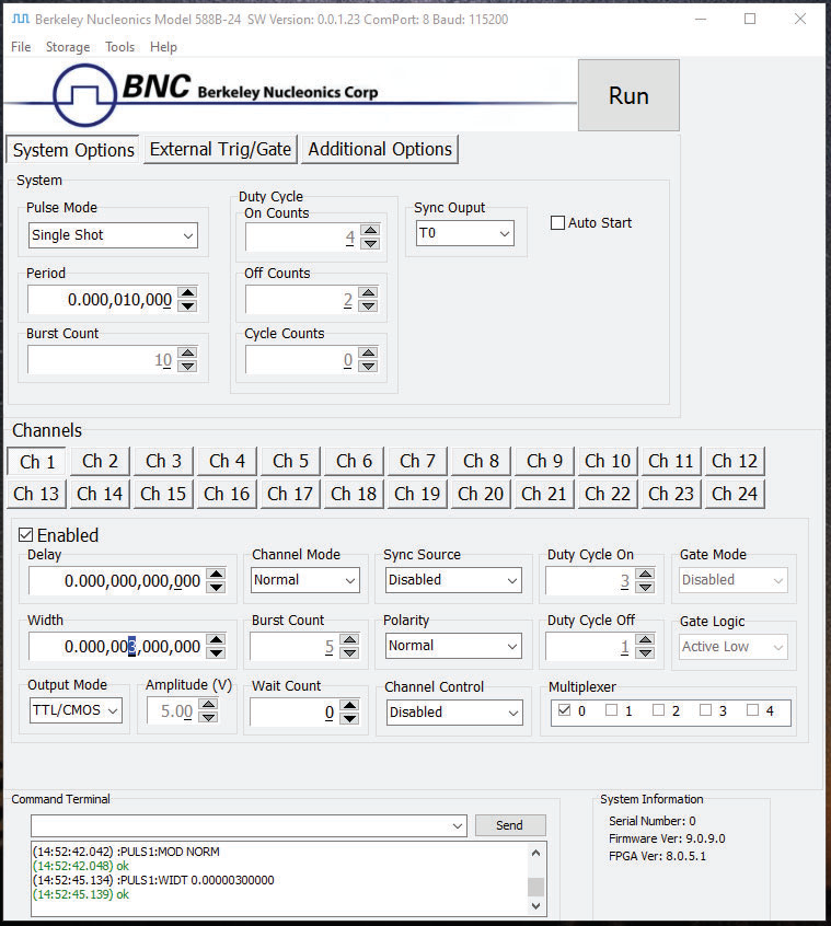
Aside from using the SCPI command protocol, the included software application is the primary means of communication with the 588B. This application allows simple control of the 588B unit via the USB or RS232 communications port. To run the software, simply double click on the application which can be found on the included USB drive. No installation is required. The software can also be copied to your computer and run from any location. The screenshot shows the 588B application and all of the corresponding default parameters:
6Programming the 588B
Personal Computer to Pulse Generator Communication
The 588B has three standard interfaces which are RS-232, USB, and an Ethernet port. All menu settings can be set and retrieved over the computer interface using a simple command language. The command set is structured to be consistent with the Standard Commands for Programmable Instruments (SCPI). Although, due to the high number of special features found in the 588B, many of the commands are not included in the SCPI specification. The syntax is the same for all interfaces. The amount of time required to receive, process, and respond to a command at a Baud rate of 115200 is 10 ms. Sending commands faster than 10 ms may cause the unit to not respond properly. All commands return a response and best practices require software to wait until the response from the previous command is received before sending the next command. This will provide fast, reliable communication with the system.
RS-232 Interface Overview
The serial port is located on the back of the 588B and uses a 9-pin D-type connector with the following pinout (as viewed from the back of the unit):
| Pin | Function |
|---|---|
| 1 | No Connection |
| 2 | Tx – Transmit (to computer) |
| 3 | Rx – Receive (from computer) |
| 4 | DTR – Connected to pin 6 |
| 5 | Ground |
| 6 | DSR – Connected to pin 4 |
| 7 | RTS – Connected to pin 8 |
| 8 | CTS – Connected to pin 7 |
| 9 | No Connection |
The serial port parameters should be set as follows:
| Baud Rate | 4800, 9600, 19200, 38400, 57600, 115200* |
| Data Bits | 8 |
| Parity | None |
| Stop Bits | 1 |
USB Interface Overview
The USB interface is standard on the 588B. The interface is a Plug-n-Play capable interface. USB communication is achieved by using a mapped (virtual) COM port on the PC. The driver installation executable will obtain an unused COM port number, install the USB drivers, and make that COM port number available for typical RS-232 communication to the pulse generator. HyperTerminal or other common software may be used.
When communicating through the mapped COM port over USB, the baud rate for the communication port used by the USB chip must match the baud rate for the COM port on the PC. Access to the USB port baud rate is done using the SCPI command :SYSTem:COMMunicate:SERial:USB "n" command; where "n" is the desired communication speed. This parameter can be accessed via any communication method. The default baud rate for USB is 38400.
USB communication notes:
- The correct drivers must be installed on the personal computer before communication can be accomplished via USB.
- The Baud Rates on the PC and the pulse generator must match for successful communication.
- The USB port's Baud Rate on the pulse generator can be set using the SCPI command
SYSTem:COMMunicate:SERial:USB "n", where "n" can be: 4800, 9600, 19200, 38400, 57600, or 115200. - USB 2.0 specification is used. The USB cable can be removed without "ejecting" the device in the operating system environment.
Ethernet Interface Overview
An Ethernet interface is also standard on the 588B. Refer to Appendix C included at the end of this manual for more information about the Ethernet Interface and Operation.
Programming Command Types and Format
The 588B Pulse Generator uses two types of programming commands: IEEE 488.2 Common Commands and Standard Commands for Programmable Instruments (SCPI). The format is the same for all interfaces. HyperTerminal (in Windows) or any other generic terminal program may be used to interactively test the commands using the RS-232 interface. The format of each type is described in the following paragraphs.
Line Termination
The pulse generator uses text-style line terminations. When a command is sent to the unit, the firmware is programmed to read characters from a communication port until it reads the line termination sequence.
The command string is parsed and executed after reading these characters. These characters are the "carriage return" and "linefeed". They are ASCII character set values 13 and 10 respectively (hex 0x0D and 0x0A). All command strings need to have these characters appended.
When the pulse generator responds to a command, whether it is a query or a parameter change, it also appends its return strings with these characters. Coded applications could use this behavior to know when to stop reading from the unit. However, if the "echo" parameter is enabled, there will be two sets of line terminators, one following the echoed command string, and one following the pulse generator's response.
The pulse generator responds to every communication string. If the communication string is a query, the unit responds with the queried response (or error code) followed by the line terminators. If the communication string is a parameter change, the response is "ok" (or error code) followed by the line terminators. For this reason, it is not recommended that multiple commands be stacked together into single strings as is common with some other types of instruments. It is recommended that the coded application send a single command in a string and follow immediately by reading the response from the unit. Repeat this sequence for multiple commands.
IEEE 488.2 Common Command Format
The IEEE 488.2 Common Commands control and manage generic system functions such as reset, configuration storage and identification. Common commands always begin with the asterisk (*) character and may include parameters. The parameters are separated from the command mnemonic by a space character. For Example:
*RST <cr><lf>*RCL 1 <cr><lf>*IDN? <cr><lf>
SCPI Command Keywords
The commands are shown as a mixture of upper- and lower-case letters. The upper-case letters indicate the abbreviated spelling for the command. You may send either the abbreviated version or the entire keyword. Upper and/or lower-case characters are acceptable.
For example, if the command keyword is given as POLarity, then POL and POLARITY are both acceptable forms; truncated forms such as POLAR will generate an error; polarity, pol, and PolAriTy are all acceptable as the pulse generator is not case sensitive.
SCPI Command Format
SCPI commands control and set instrument specific functions such as setting the pulse width, delay, and period. SCPI commands have a hierarchical structure composed of functional elements that include a header or keywords separated with a colon, data parameters, and terminators. For example:
:PULSE1:STATE ON <cr><lf>:PULSe1:WIDTh 0.000120 <cr><lf>:PULSe:POL NORMal <cr><lf>
Any parameter may be queried by sending the command with a question mark appended. For example:
| SCPI Query Format | Will Return |
|---|---|
:PULSE1:STATE? <cr><lf> | 1 <cr><lf> |
:PULSE1:WIDTH? <cr><lf> | 0.000120000 <cr><lf> |
:PULSE1:POL? <cr><lf> | NORM <cr><lf> |
SCPI Keyword Separator
A colon (:) must always separate one keyword from the next lower-level keyword. A space must be used to separate the keyword header from the first parameter.
SCPI Optional Keywords
Optional keywords and/or parameters appear in square brackets ( [ ] ) in the command syntax. Note that the brackets are not part of the command and should not be sent to the pulse generator. When sending a second level keyword without the optional keyword, the pulse generator assumes that you intend to use the optional keyword and responds as if it had been sent.
SCPI Specific and Implied Channel
Some commands, such as PULSe, allow specifying a channel with an optional numeric keyword suffix. The suffix will be shown in square brackets [ 1 / 2 ]. The brackets are not part of the command and are not to be sent to the pulse generator. The numeric parameters correspond to the following channels: 0 = T0, 1 = ChA, 2 = ChB, etc. Only one channel may be specified at a time.
If you do not specify the channel number, the implied channel is specified by the :INSTrument:SELect command or the last referenced channel. After power-up or reset (*RST) the instrument will default to channel #1.
SCPI Parameter Types
The following parameter types are used:
| <Numeric Value> | Accepts all commonly used decimal representation of numbers including optional signs, decimal points, and scientific notation. For Example: 123, 123e2, -123, -1.23e2, .123, 1.23e-2, 1.2300E-01. |
| <Boolean Value> | Represents a single binary condition that is either true or false. True is represented by a 1 or ON; false is represented by a 0 or OFF. Queries return 1 or 0. |
| <Identifier> | Selects from a finite number of predefined strings. |
Error Codes
The unit responds to all commands with either ok <cr><lf> or ?"n" <cr><lf> where "n" is one of the following error codes:
- Incorrect prefix, i.e. no colon or * to start command.
- Missing command keyword.
- Invalid command keyword.
- Missing parameter.
- Invalid parameter.
- Query only, command needs a question mark.
- Invalid query, command does not have a query form.
- Command unavailable in current system state.
Programming Examples
Example 1
20 ms pulse width, 2.3 ms delay, 10 Hz internal trigger, and continuous operation.
| Command | Description |
|---|---|
:PULSE1:STATE ON <cr><lf> | enables channelA |
:PULSE1:POL NORM <cr><lf> | sets polarity to active high |
:PULSE:WIDT 0.020 <cr><lf> | sets pulse width to 20 ms |
:PULSE1:DELAY 0.0023 <cr><lf> | sets delay to 2.3 ms |
:PULSE0:MODE NORM <cr><lf> | sets system mode to continuous |
:PULSE0:PER 0.1 <cr><lf> | sets period to 100 ms (10 Hz) |
:TRIG:STATE DIS <cr><lf> | disables the external trigger |
:PULSE0:STATE ON <cr><lf> | starts the pulses |
:INST:STATE ON <cr><lf> | alternate form to start pulses |
Example 2
25µs pulse width, 0 delay, external trigger, and one pulse for every trigger.
| Command | Description |
|---|---|
:PULSE1:STATE ON <cr><lf> | enables channelA |
:PULSE1:POL NORM <cr><lf> | sets polarity to active high |
:PULSE:WIDT 0.000025 <cr><lf> | sets pulse width to 25µs |
:PULSE1:DELAY 0 <cr><lf> | sets delay to 0 |
:PULSE0:MODE SING <cr><lf> | sets system mode to single shot |
:TRIG:STATE ENAB <cr><lf> | sets system to external trigger |
:TRIG:LEV 2.5 <cr><lf> | sets trigger level to 2.5 volts |
:TRIG:EDGE RIS <cr><lf> | set to trigger on rising edge |
:PULSE0:STATE ON <cr><lf> | Arms the instrument |
:INST:STATE ON <cr><lf> | Alternate form if T0 is currently selected. |
*TRG <cr><lf> | Generates a software external trigger |
588B SCPI Command Summary
| Keyword / Command | Parameter Range | Notes |
|---|---|---|
:INSTrument | Submenu: Misc. system commands. | |
:COMMands? | ? | Returns an indentured list of all valid SCPI commands. |
:NSELect | 0 – n | Selects a channel using the numeric value, where 'n' is the number of channels (6, 12, 24). |
:STATe | 0/1 or OFF/ON | Enables/Disables the selected channel output. If no channel has been selected the command is applied to T0. If T0 is selected all outputs are affected. Enabling T0 is the same as pressing the RUN button. |
:SPULse / :PULSe0 | Submenu: Commands to change the system timer settings. Can use either :SPULse or :PULSe0. | |
:STATe | 0/1 or OFF/ON | Enables/Disables the output for all channels. This command is the same as pressing the Run/Stop button. |
:PERiod | 50[ns] – 5000[s] | Sets the T0 period. The command should be sent without units. If for example 100µs is desired the parameter sent should be 0.0001 or using exponential notation i.e. 100e-6. |
:MODe | NORMal / SINGle / BURSt / DCYCle | Changes the system output mode. |
:BCOunter | 1 – 4,000,000,000 | Changes the number of pulses to output when the system is in burst mode. Do not include commas. |
:PCOunter | 1 – 4,000,000,000 | Changes the number of on pulses to output when the system is in Duty Cycle mode. Do not include commas. |
:OCOunter | 1 – 4,000,000,000 | Changes the number of off pulses to suppress when the system is in Duty Cycle mode. Do not include commas. |
:CYCLe | 0 – 10,000,000 | Changes the number of cycles to output when the system is in Duty Cycle mode, 0 = continuous cycles. Do not include commas. |
:TRIGger[1/2] | Submenu: Commands to change the system trigger functions. Trig1 is the rear panel trigger input and Trig2 is the front panel input. | |
:MODe | DISable / TRIGger | Enables the global trigger mode for the unit: When the unit is set to single pulse each trigger input will produce an output pulse; when in burst mode each trigger input will produce a burst of output pulses; and when in continuous or duty cycle mode the trigger input will start the pulses (the trigger will function the same as pressing the Run/Stop button). |
:EDGe | RISing / FALLing | Choose the edge of the incoming pulse to trigger on. |
:LEVel | .20 – 15[V] | Choose the gate level threshold to trigger on, this should be set to ~50% of the input potential. |
:DEBounce | ENABle / DISable | Enables / disables the circuit. Note: This will increase the insertion delay. |
:GATe[1/2] | Submenu: Commands to change the system gate functions. Gate1 is the rear panel gate input and Gate2 is the front panel input. | |
:MODe | DISabled / PULSe / OUTPut / CHANnel | Sets the global gate mode for the unit: When in pulse inhibit mode if the pulse has started before the gate is seen the output pulse will finish, but any further pulses will be prevented; in output inhibit mode if a pulse has started it will be truncated as soon as the gate signal is seen and will prevent any further pulses; and when in channel mode each channel can be set up individually (be aware of insertion delay for each mode, this is listed in the appendix). |
:LOGic | LOW / HIGH | Choose active Low (will allow pulses when low) or active High (will allow pulses when high). |
:LEVel | .20 – 15[V] | Choose the gate level threshold to trigger on, this should be set to ~50% of the input potential. |
:DEBounce | ENABle / DISable | Enables / disables the circuit. Note: This will increase the insertion delay. |
:COUNter :STATe | 0/1 or OFF/ON | Enables / disables the counter. |
:CLear | 1 | Clears the counter. Should be done before starting a count. |
:SELect | To / CH1 / CH2 / CH4 / CH6 | Selects channel to count. |
:PULSes | ? | Returns the current count. |
:PULSe[1/2/n] | Submenu: Commands to change the channel settings. 'n' is the channel number. | |
:STATe | 0/1 or OFF/ON | Enables/Disables output pulse for selected channel. |
:DELay | 0[s] to 2000[s] | Sets the delay for the selected channel. The command should be sent without units. If for example 25µs is desired the parameter sent should be 0.000025 or using exponential notation i.e. 25e-6. |
:WIDTh | 10[ns] – 2000[s] | Sets the pulse width for the selected channel. The command should be sent without units. If for example 50ns is desired the parameter sent should be 0.00000050 or using exponential notation i.e. 50e-9. |
:MODe | NORMal / SINGle / BURSt / DCYCle | Allows the user to select the pattern of outputs to use on the channel level. |
:BCOunter | 1 to 10,000,000 | In Burst mode allows user to select the number of pulses to output with each input clock pulse. Do not include commas. |
:PCOunter | 1 to 10,000,000 | In duty cycle mode allows the user to select the number of pulses to create with each input clock pulse. Do not include commas. |
:OCOunter | 1 to 10,000,000 | In duty cycle mode allows the user to select the number of pulses to suppress with each input clock pulse. Do not include commas. |
:WCOunter | 0 to 10,000,000 | Allows the user to select how many T0 pulses to wait until the channel should start creating output pulses. Do not include commas. |
:OUTPut | Submenu: Commands to change the channels' output parameters. | |
:MODe | TTL / ADJustable | Allows the user to select either TTL logic mode or Adjustable voltage output mode. |
:POLarity | NORMal / COMPlement / INVerted | Normal is active HIGH, Inverted and Complement are active LOW. |
:AMPLitude | 2.0 to 20[V] | Allows the user to select the voltage potential for Adjustable output mode. |
:MUX | 0 to 31 | Routes channel timers to the output (see Digital Output Multiplexer). |
:CONTrol | DISable / GATA / GATB / INHB | Enables gate / inhibit function: GATA (ch8) as a global gate. GATB (ch12, 24 or 36) as a bank gate. INHB (ch12, 24 or 36) as a bank inhibit. |
:SYNC | DISabled / SYNA / SYNB / SYNT | Enables sync function. SYNA (ch10) as a global sync. SYNB (ch12, 24, or 36) as a bank sync. SYNT (trig) as a global sync. |
:CGATe | DISabled / PULSe / OUTPut | Sets the channel gate mode to Disabled, Pulse Inhibit mode, or Output Inhibit mode. Note: The system global gate mode must be set to CHAN for this command. |
:CLOGic | LOW / HIGH | Set the channel gate to active LOW or active HIGH. Note: The system global gate mode must be set to CHAN for this command to work. |
:SYSTem | Submenu: Commands to change general system settings. | |
:STATe | 0 / 1 or OFF / ON | Enables/Disables the output for all channels. This command is the same as pressing the Run/Stop button. |
:SYNC | T0 / Ch1 / Ch2 / Ch4 / Ch6 / TRIG / GATE | Selects front panel sync output. |
:ICLock | Submenu: Commands for selecting the system timer oscillator source. | |
:ICLOCK | INT / 10 / 20 / 25 / 30 / 40 / 50 / 60 / 80 | Changes the source of the system clock. INT is internal; 'n' is the input frequency in MHz. |
:OCLOCK | T0 / 10 / 20 / 25 / 30 / 40 / 50 / 60 / 80 | Allows the user to select the clock source to output. When ICLock is INT: T0 is the system sync pulse; 'n' is the input frequency in MHz. |
:BEEPer | Submenu: Commands to change the units' beeper settings. | |
:STATe | 0/1 or OFF/ON | Command to turn on or off the systems' beeper. |
:VOLume | 0 – 100 | Command to change the units' beeper volume. |
:COMMunicate | Submenu: Command to set the communication settings. | |
:BAUD | 4800 / 9600 / 19200 / 38400 / 57600 / 115200 | Command to change the baud rate for the RS-232 interface. |
:USB | 4800 / 9600 / 19200 / 38400 / 57600 / 115200 | Command to change the baud rate for the USB interface. |
:ECHo | 0/1 or OFF/ON | Command to Enable/Disable the echo function on the RS-232 interface. The Echo function will cause the unit to repeat the command received to the PC. |
:KLOCk | 0/1 or OFF/ON | Command to lock-out the keypad. |
:AUTorun | 0/1 or OFF/ON | When the unit is powered up, if this command is enabled, the unit will start pulsing automatically. |
:VERSion | ? | Query only. Returns SCPI version number in the form YYYY.V for ex. 1999.0. |
:SERNumber | ? | Query only. Returns the serial number of the unit. The format returned will be "SER# xxxxx". |
:INFOrmation | ? | Query only. Returns model, serial number, firmware version, and FPGA version numbers. The same as the *IDN? Command. |
:NSID | ? | Query only. Returns firmware and FPGA identification numbers. |
:CAPS | 0/1 or OFF/ON | The default value is 1, which means the unit is not case sensitive. 0 means the commands sent to the unit must be capitalized. Note: To change this parameter the unit must be power cycled before the command will take effect. |
IEEE 488.2 Common Commands
| Command | Parameter Range | Notes |
|---|---|---|
| System Commands | ||
*BEP | 1 to 1000; 1 to 100 | Generates a beep, first parameter is the volume, second parameter is the number of beeps to produce. |
*LOG | 0 to 100 | Controls the brightness of the front panel logo. |
*CAT | ? | Query only. Generates an indentured list of all SCPI commands. |
*ERS | Resets the ethernet port. | |
*IDN | ? | Query only. Returns model, serial number, firmware version, and FPGA version numbers. |
| Storage Commands | ||
*LBL | ? / String Value | Used to query the label of the last saved or recalled configuration. Command to attach a string label to the current settings. The string must be in double quotes and no longer than 14 characters. Command must be followed by a *sav [1/2/n] command to take effect. Note: To see the label on the screen a display update or reboot must take place. |
*RCL | 0 – n | Recall the saved configuration. 'n' depends on the model (6/12 channel units n = 12, 24 channel unit n = 24). *RCL 0 loads the system default values. |
*SAV | 1 – n | Save a configuration. 'n' depends on the model (6/12 channel units n = 12, 24 channel unit n = 24). |
*RST | Resets the unit to the default values. This is the same as *RCL 0. | |
*PUP | 0 – n | PowerUP configuration. Sets the configuration to be loaded on power up. 0 = The configuration that was stored on power down. n = The configuration #. |
| Quick Setup Commands | ||
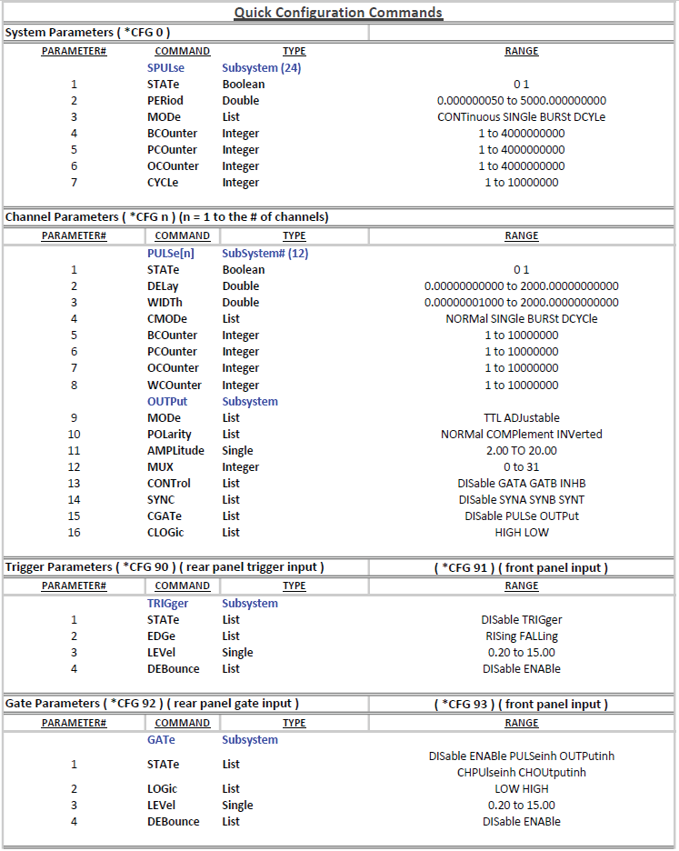
*CFG | 0 [p1] [p2] ... | Provides a more efficient way of loading parameters. *CFG 0 loads the system timer parameters. See description below. |
*CFG | n [p1] [p2] ... (n is the ch#) | Provides a more efficient way of loading parameters. *CFG n, where 'n' is the channel number, loads the channel parameters. See description below. |
*CFG | 90 | Loads the trigger 1 parameters for the rear trigger input. See description below. |
*CFG | 91 | Loads the trigger 2 parameters for the front panel input. See description below. |
*CFG | 92 | Loads the gate 1 parameters for the rear panel gate input. See description below. |
*CFG | 93 | Loads the gate 2 parameters for the front panel input. See description below. |
| Trigger Commands | ||
*ARM | 0/1 or OFF/ON | Resets all channel counters simultaneously when the channels are in either single shot or burst mode. Note: The system must be in continuous mode (this command is functionally the same as pressing the Run/Stop button). |
*GTE | Creates a soft trigger for the gate input. | |
*TRG | Creates a soft trigger for the trigger input. | |
| Counter Commands | ||
*CTR | 0 to 5, 10 | n = 0 disables the counter. n > 0 selects a channel, clears the counter & enables counter. n=1 -> T0, n=2 -> Ch1, n=3 -> Ch6, n=4 -> Ch8, n=5 -> Ch10. n=10 re-enables counter without clearing, uses current channel for source. *CTR? returns the current counter value. |
Config Command (*CFG)
*CFG ch# [parameter 1] [parameter 2] [parameter 3] ... [parameter n]
ch# = channel number, 0 = System parameters, 9x = Trigger / Gate parameters. The parameter list (partial list) is terminated by a line feed or a carriage return.
7Appendix A – Specifications
Internal Rate Generator
| Rate (T0 period) | 50ns to 5,000s (0.0002 Hz to 20.000 MHz) |
| Resolution | 5 ns |
| Accuracy | 1 ns + .0001 x period |
| Jitter | < 50 ps RMS |
| Settling | 1 period |
| Burst Mode Counter | 1 to 4,000,000,000 pulses |
| Duty Cycle Mode Counters | 1 to 4,000,000,000 pulses |
| Cycle Counter | 1 to 10,000,000 cycles |
| Timebase | 200 MHz, low jitter PLL |
| Oscillator | 50 MHz, 25 ppm |
| System Output Modes | Single pulse, burst, duty cycle, external gate/trigger |
| Pulse Control Modes | Internal rate generator, external trigger/gate |
Channel Timing Generator
| Channel Output Modes | Single shot, burst, duty cycle, normal |
| Control Modes | Internally triggered, externally triggered and external gate. Each channel may be independently set to any of the modes. |
| Burst Mode Counter | 1 to 10,000,000 pulses |
| Duty Cycle Mode Counters | 1 to 10,000,000 pulses |
| Wait Function Counter | 0 to 10,000,000 pulses |
| Output Multiplexer | Up to five (5) channel timers may be routed to each output channel. |
| Timebase | Same as internal rate generator |
Delays
| Delay Range | 0 – 2,000 s |
| Width Range | 10ns – 2,000s |
| Accuracy | 1 ns + 0.0001 x Delay |
| Resolution | 250 ps |
| Pulse Inhibit Delay | < 120 ns typical |
| Output Inhibit Delay | < 50 ns typical |
Output Module Specifications
TTL/Adjustable Dual Channel Output Module (Standard).
| Output Impedance | 50 ohm |
| TTL/CMOS Mode | |
| Output Level | 4.0 V typ into 1 kohm |
| Rise Time | 3 ns typ (10% – 90%) |
| Slew Rate | > 0.5 V/ns |
| Jitter | 50 ps RMS channel to channel |
| Adjustable Mode | |
| Output Level | 2.0 to 20 VDC into 1 kohm; 1.0 to 10.0 VDC into 50 ohm |
| Output Resolution | 10 mV |
| Current | 200 mA typical, 400 mA (short pulses) |
| Rise Time | 15 ns typ @ 20 V (high imp); 25 ns typ @ 10 V (50 ohms) (10% – 90%) |
| Slew Rate | > 0.1 V/ns |
| Overshoot | < 100 mV + 10% of pulse amplitude |
System External Trigger/Gate Input(s)
| Trigger Input | |
| Type | Pulse 0.5 to 30v, switch closure (footswitch, safety interlock, etc.) |
| Function | Generate individual pulses, start a burst or continuous |
| Rate | DC to 1 / (200 ns + longest active pulse). Maximum of 5 MHz |
| Slope | Rising or Falling |
| Gate Input | |
| Mode | Pulse inhibit or output inhibit |
| Polarity | Active high / active low |
| Channel Behavior | Global w/ Individual Channel Control |
| Trigger/Gate Dual Input Module (Standard) | |
| Standard dual channel input module, providing one trigger input, one gate input and one dual purpose input on the front panel. | |
| Threshold | 0.2 to 15 VDC |
| Maximum Input Volt. | 30 V Peak |
| Impedance | 5.3 K ohm + 10pF |
| Resolution | 10 mV |
| Trigger Input Slope | Rising or Falling |
| Trigger Input Jitter | 800 ps RMS |
| Trigger Input Insertion Delay | < 160 ns |
| Trigger Input Minimum Pulse Width | 10 ns |
| Gate Input Pulse Inhibit Delay | < 160 ns |
| Gate Input Output Inhibit Delay | < 160 ns |
Standard Features
| Communications | USB / RS232 / Ethernet |
| External Clock In | 10 MHz, 20 MHz, 25 MHz, 30 MHz, 40 MHz, 50 MHz, 60 MHz, 80 MHz |
| External Clock Out | T0, 10 MHz, 20 MHz, 25 MHz, 30 MHz, 40 MHz, 50 MHz, 60 MHz, 80 MHz, 100 MHz |
General
| Storage | 12 ch = 12 storage bins; 24 ch = 24 storage bins |
| Dimensions | 19" x 10" x 3.50" 12/24 ch (standard 2U rack mount) |
| Weight | 8 lbs |
| Power | 100 – 240 VAC, 50/60 Hz, < 3 A |
| Fuse | (Qty 2) 630 mA, 250 V Time-lag |
588B Mechanical Dimensions
8Appendix B – Safety Symbols
Safety Marking Symbols
Technical specifications including electrical ratings and weight are included within the manual. See the Table of Contents to locate the specifications and other product information. The following classifications are standard across all BNC products:
- Indoor use only
- Ordinary Protection: This product is NOT protected against the harmful ingress of moisture.
- Class 1 Equipment (grounded type)
- Main supply voltage fluctuations are not to exceed ±10% of the nominal supply voltage.
- Pollution Degree 2
- Installation (overvoltage) Category II for transient overvoltages
- Maximum Relative Humidity: < 80% RH, non-condensing
- Operating temperature range of 0°C to 40°C
- Storage and transportation temperature of -40°C to 70°C
- Maximum altitude: 3000 m (9843 ft.)
- This equipment is suitable for continuous operation.
This section provides a description of the safety marking symbols that appear on the instrument. These symbols provide information about potentially dangerous situations which can result in death, injury, or damage to the instrument and other components.
| Publication | Description / Comment |
|---|---|
| IEC 417, No. 5031 | Direct current. Vdc may be used on rating labels. |
| IEC 417, No. 5032 | Alternating current. For rating labels, the symbol is typically replaced by V and Hz as in 230V, 50Hz. DO NOT USE Vac. |
| IEC 417, No. 5033 | Both direct and alternating current. |
| IEC 617-2 No. 02-02-06 | Three-phase alternating current. |
| IEC 417, No. 5017 | Earth (ground) terminal. Primarily used for functional earth terminals which are generally associated with test and measurement circuits. These terminals are not for safety earthing purposes but provide an earth reference point. |
| IEC 417, No. 5019 | Protective conductor terminal. This symbol is specifically reserved for the protective conductor terminal and no other. It is placed at the equipment earthing point and is mandatory for all grounded equipment. |
| IEC 417, No. 5020 | Frame or chassis terminal. Used for points other than protective conductor and functional earth terminals where there is a connection to accessible conductive terminals to advise the user of a chassis connection. |
| IEC 417, No. 5021 | Equipotentiality. Used in applications where it is important to indicate to the operator that two or more accessible functional earth terminals or points are equipotential. More for functional rather than for safety purposes. |
| IEC 417, No. 5007 | On (Supply). Note that this symbol is a bar, normally applied in the vertical orientation. It is not the number 1. |
| IEC 417, No. 5008 | Off (Supply). Note that this symbol is a true circle. It is not the number 0 or the letter O. |
| IEC 417, No. 5172 | Equipment protected by double insulation or reinforced insulation (equivalent to Class II of IEC 60536). |
| ISO 3864, No. B.3.6 (background yellow; symbol and outline black) | Caution, risk of electric shock. Generally used only for voltages in excess of 1000 V. It is permissible to use it to indicate lower voltages if an explanation is provided in the manual. Color requirements do not apply to markings on equipment if the symbol is molded or engraved to a depth or raised height of 0.5 mm, or that the symbol and outline are contrasting in color with the background. |
| IEC 417, No. 5041 (background yellow; symbol and outline black) | Caution, hot surface. Color requirements do not apply to markings on equipment if the symbol is molded or engraved to a depth or raised height of 0.5 mm, or that the symbol and outline are contrasting in color with the background. |
| ISO 3864, No. B.3.1 (background yellow; symbol and outline black) | Caution (refer to accompanying documents). Used to direct the user to the instruction manual where it is necessary to follow certain specified instructions where safety is involved. Color requirements do not apply to markings on equipment if the symbol is molded or engraved to a depth or raised height of 0.5 mm, or that the symbol and outline are contrasting in color with the background. |
| IEC 417, No. 5268-a | In-position of bistable push control. |
| IEC 417, No. 5269-a | Out-position of bistable push control. |
9Appendix C – Ethernet Connectivity
The Ethernet module used in Berkeley Nucleonics Corporation's pulse generators is a "Digi Connect ME" device manufactured by Digi International, Inc. It supports virtually all practical Ethernet communication methods. A set of utilities and documentation by Digi is included on the CD/USB shipped with the pulse generator. This discussion assumes that the Digi utilities included with your pulse generator and National Instruments VISA (version 3.3 in this procedure, see National Instruments' website) are installed.
Determining IP Address
The Digi module has been reset to factory defaults before it left the manufacturing facility. In this mode, it is ready to be assigned an IP address by the local DHCP server. If a crossover cable is being used, the Ethernet device will assume a default IP address.
The Digi utility "Digi Device Discovery" can be used to determine the IP address that is currently assigned to the Ethernet module. Hit "Start, All Programs, Digi Connect, Digi Device Discovery". When the utility opens, it scans the LAN looking for Digi Ethernet modules. It may take a minute after plugging in or powering the Ethernet module before the LAN negotiates the connection with the Digi module. Hit "Refresh View" in the left column after a minute or so if the utility fails to see the unit when you start it. When the utility sees the Digi device, it will display it in the list (Figure 8).
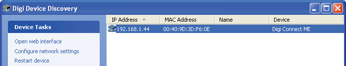
Note the IP address for use later. A static IP address can be set using the "Configure network settings" link in the left hand column. From this point, a web interface can be opened, allowing access to configuration options for the Digi module. Select "Open web interface" under the device tasks on the left hand column of the Digi Device Discovery software.
You will be required to enter a username and password. Units built after January 2021 will have a unique password for each unit. The password can be found on the paperwork shipped with the device and there will also be a label on the device indicating the password.
- Username: "root"
- Password: <unit specific>
The Digi Connect ME Configuration and Management home page will be displayed (Figure 9).
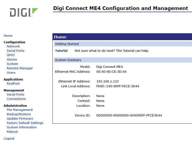
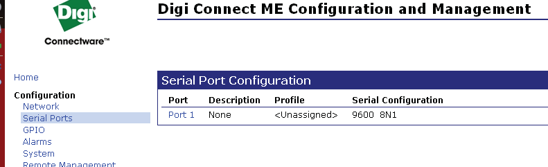
From the home page select "Serial Ports" on the left hand side. The serial port configuration page will be displayed (Figure 10).
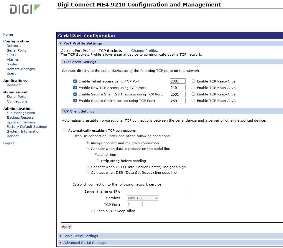
Select Port 1 from the list of ports. The Port Profile Settings will then be displayed. Be sure that the box next to "Enable Raw TCP access using TCP Port:" is selected and note the port number. By default the port number is 2101. Then change the current port profile by selecting the "Change Profile..." link (Figure 11).
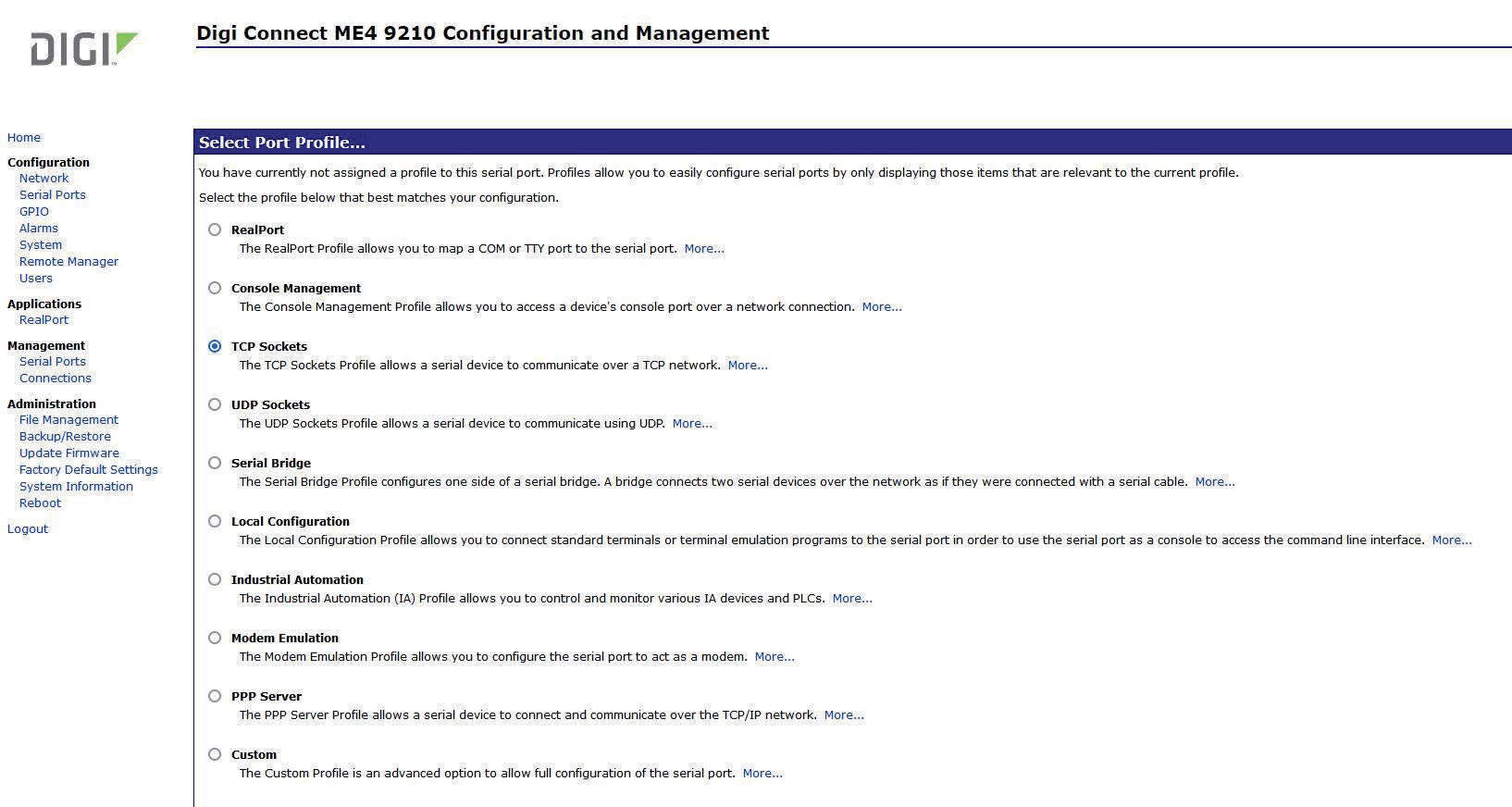
Select TCP Sockets from the list of available profiles and click on apply at the bottom of the page (Figure 12).
Next, select the "Basic Serial Settings" section located below the "Port Profile Settings" section. Set the baud rate to 115200 (Figure 13).
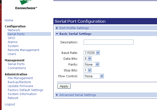
Click on apply after changing the baud rate. Select "Logout" from the bottom of the left hand column. After logging out, power cycle the instrument. Use the Digi Device Discovery software to see if the IP address of the unit appears again. Once the unit has been identified the unit is ready for communication.
Testing Ethernet Communication
Ethernet communication to the pulse generator can be tested using any terminal utility that supports TCPIP. Two options are the "VISA Interactive Control" that is installed with National Instruments VISA libraries and another is PuTTY.
VISA Interactive Control Example
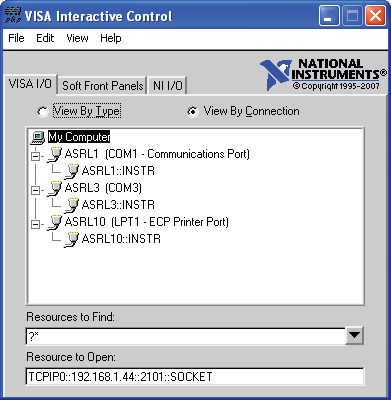
After determining the IP address for the unit, "VISA Interactive Control" can be used to send and receive command strings to and from the pulse generator. The VISA Interactive Control can be found installed in the National Instruments program group. When this utility opens, it displays local resources found. TCPIP resources are typically not shown in this window. However, the resource string can be successfully entered manually in the "Resource to Open" field (Figure 14). The resource string for Digi Connect Ethernet Modules in Berkeley Nucleonics Corporation pulse generators needs to be formatted as follows:
TCPIP0::<IP address>::2101::SOCKET
Or, for example: TCPIP0::192.168.1.44::2101::SOCKET
A session window will open allowing access to communication parameters and read and write buffer access and control. Berkeley Nucleonics Corporation units support SCPI formatted command strings. For these units, command strings and responses are both terminated with text-style line terminations, a carriage return and linefeed pair. These are ASCII characters number 13 and 10 respectively. They are represented in this utility (and in many other contexts) as "\r\n". In hexadecimal, these are represented as "0x0D" and "0x0A", respectively. When sending command strings to the pulse generator, strings need to be terminated with a carriage return and linefeed pair. Without this line termination, the pulse generator will not execute commands, but continue to wait for more characters until it sees this string termination sequence.
Select the "Write" tab (Figure 15).
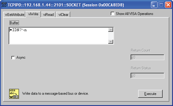
The "Buffer" field can be edited to send any valid command to the pulse generator. Hit "Execute" to send the "*IDN?" command. Now select the "Read" tab (Figure 16).
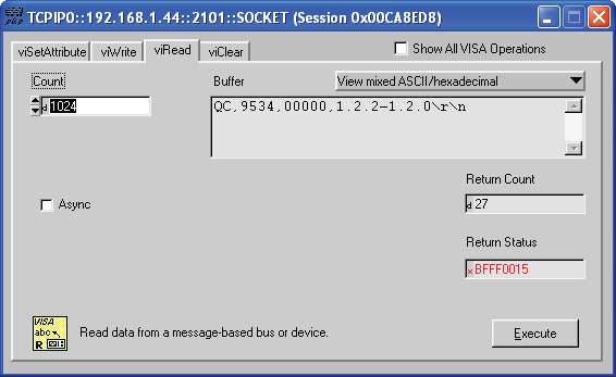
Successive iterations between "Write" and "Read" operations can be accomplished from here. Keep in mind that it is always best to follow each "Write" command immediately with a "Read" command, whether the commands are generated from a utility such as this, or from a more complex coded application. The pulse generator is designed to respond to every command line with either the result of a query (ie, ":pulse1:width?\r\n" could return "0.000100000"), or a simple "ok\r\n" to acknowledge a successful parameter change. If a "Read" command does not follow each "Write" command, the read (output) buffer in the pulse generator can overfill and become corrupt.
PuTTY Example
PuTTY is an open source terminal emulator that can be used for various methods of communications. Once PuTTY is installed and run for the first time, a few parameters need to be entered before communications with the unit can be established (Figure 17).
- Host Name (or IP Address): Enter the IP address of the unit determined by using the Digi Device Discovery utility as described previously.
- Port: Enter the port number of the device as set during the device configuration. Default is 2101.
- Connection type: Select Raw.
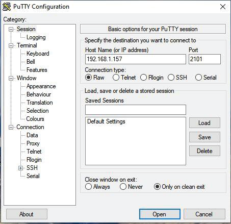
Select Open and a new window will appear (Figure 18). In this window, commands or queries can be sent to the unit. In the example, an *IDN? query is sent. Once enter is pressed, a response should be received.
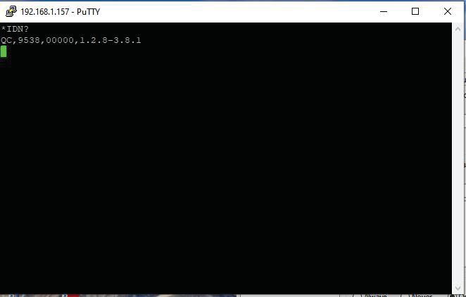
Many applications may need a communication mechanism no more sophisticated than what can be achieved with these simple utilities. At the very least, these tools can be used to verify that the pulse generator and communication hardware are functioning properly. From here, a specific application in whatever preferred programming language can be built.
10Appendix F – Impedance Matching Outputs
TZ50 Impedance Matching Output Module
This module option allows a user to have a 50 Ω load on the output while maintaining output amplitude of at least 4 Volts while in the TTL/CMOS mode. All other functionality of the module is the same as the AT20 modules, including output while using the Adjustable Mode Function of the channels.
TTL/Adjustable Outputs
| TTL/CMOS Mode | |
| Output Level | 4.0 Volts typical into 50 Ω |
| Rise Time | 3 ns |
| Slew Rate | > 0.5 V/ns |
| Jitter – Channel to Channel | < 50 ps RMS |
| Adjustable Mode | |
| Output Resolution | 10 mV |
| Current | 200 mA typical, 400 mA max (short pulses) |
| Slew Rate | > 0.1 V/ns |
11Appendix H – External Clock
588B External Clock Operation
The 588B pulse generator can utilize an external clock input to synchronize instrument timing. The following specifications must be met in order for proper external clock operation.
| Parameter | Minimum | Maximum |
|---|---|---|
| Pulse Width | 5ns | – |
| Pulse Amplitude | 3.3 Vrms | 5 Vrms |
| Input Impedance | > 10 KΩ | – |
| Frequency | 10 MHz | 100 MHz |
| Jitter, Cycle to Cycle | – | ± 300 ps |
| Jitter, Period | – | ± 1 ns |
| Pulse Width Duty Cycle | 45% | 55% |
12Support / Contact
For technical support, warranty service, or questions about operating the Model 588B, contact Berkeley Nucleonics Corporation:
- Phone: (415) 453-9955
- Email: info@berkeleynucleonics.com
- Web: www.berkeleynucleonics.com
- Berkeley Nucleonics Corporation, 2955 Kerner Blvd., San Rafael, CA 94901