1Overview
The PCX-7401 is a pulsed precision current source built to drive laser diodes, diode bars, and arrays with clean, repeatable current pulses. It produces both a pulsed output and a separate bias output, so the diode can be held just below threshold and then pulsed above it. Output current is programmable from 0 to 3 A, with bias current programmable from 0 to 0.550 A, both set in 1 mA steps.
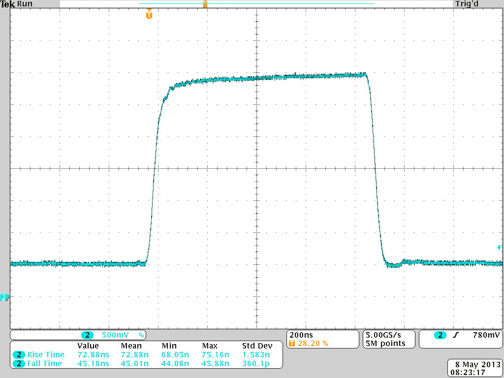
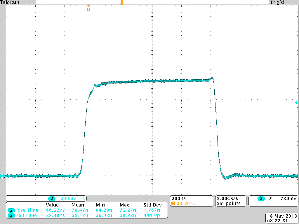
A modern internal trigger source runs in two modes, duty cycle and single shot, while an external trigger input adds flexibility for synchronization with the rest of a test setup. Pulse widths span 100 ns to DC, and the internal trigger covers 5 Hz to 1 MHz. Rise and fall times stay at or below 100 ns, with cycle-to-cycle jitter at or below 25 ns.
Directed Energy, Inc. is now a division of Berkeley Nucleonics. The PCX-7401 is the same design, built in California, with one support path. Operation is straightforward through the front-panel controls and a color LCD touchscreen, and every configuration can be saved to non-volatile memory for instant recall.
2How It Works
A laser diode driver is a current source, not a voltage source. The PCX-7401 regulates the current delivered to the diode and reports the compliance voltage as the maximum voltage available to maintain that programmed current. Holding current flat through the pulse is what preserves optical pulse fidelity, so the instrument is specified end to end with a low-inductance stripline interconnect of less than 4 nH total inductance.
In duty-cycle mode, the internal trigger sets repetition rate and duty cycle and the source pulses continuously. In single-shot mode, the instrument fires one pulse of a defined width on command. When the pulsed bias output is used, a fixed bias pulse is applied for a short interval before and after the main pulse, so the diode sees a controlled current floor around each shot rather than a hard edge from zero.
3Pulse & Bias Amplitude
All specifications are measured with a low-inductance stripline interconnect cable of less than 4 nH total inductance to the laser diode. The PCX-7401 meets or exceeds these specifications.
| Pulse amplitude | Specification |
|---|---|
| Output current range | 0.000 A to 3.000 A |
| Setpoint resolution | 0.001 A |
| Setpoint accuracy1 | plus or minus 0.001 A |
| Compliance voltage | 15 V or less |
| Overshoot | Less than 2% |
| Maximum output power | 54 W |
| Bias amplitude | Specification |
|---|---|
| Bias current amplitude | 0.000 A to 0.550 A |
| Bias current resolution | 0.001 A |
| Bias current accuracy | plus or minus 0.001 A |
4Output & Trigger Specifications
| Output parameters | Specification |
|---|---|
| Pulse width range | 100 ns to DC |
| Rise/fall time | 100 ns or less |
| Polarity | Positive |
| Internal trigger | Specification |
|---|---|
| Frequency range | 5 Hz to 1.000 MHz |
| Frequency resolution | 5 Hz (5 Hz to 995 Hz); 100 Hz (1 kHz to 49.9 kHz); 1000 Hz (50 kHz to 1 MHz) |
| Frequency accuracy | plus or minus (0.01 × setpoint + 2) Hz |
| Cycle-to-cycle jitter, Tjit(cc) | 25 ns or less |
| Duty cycle range | 1% to 99% |
| Duty cycle resolution | 0.01% |
| Duty cycle accuracy | plus or minus (0.01 × setpoint + 2.5)% |
| Internal single-shot trigger | Specification |
|---|---|
| Pulse width range | 200 ns to 1.0000 s |
| Pulse width resolution | 100 ns (200 ns to 5,000 ns); 1 us (6 us to 1,000 ms) |
| Pulse width accuracy | plus or minus 5 ns (200 ns to 5,000 ns), grading to plus or minus 2,000 us (100.001 ms to 1,000 ms) |
| Pulsed bias output2 | Fixed bias width |
|---|---|
| Main pulse 200 ns to 100 us | 2 us |
| Main pulse 100.1 us to 350 us | 10 us |
| Main pulse 350.1 us to 1,000 ms | 25 us |
| External trigger | Specification |
|---|---|
| Frequency range | 2,000,000 Hz or less |
| Minimum pulse width | 100 ns |
| Delay (external to output) | Approximately 130 ns |
| Termination impedance | 50 ohm or 10 kohm |
| Connector | BNC |
| Input voltage levels | 0 V to 5 V; 5 V = output to load, 0 V = no output to load |
| Trigger sync output | Specification |
|---|---|
| Termination | Requires 50 ohm |
| Connector | BNC |
| Output voltage levels | 0 V to 4.5 V |
| Delay (sync to output) | Approximately 100 ns |
5General Specifications
| Parameter | Specification |
|---|---|
| Power requirements | 47 Hz to 63 Hz; 100 VAC to 120 VAC plus or minus 10%, or 220 VAC to 240 VAC plus or minus 10% |
| AC inrush current (typical) | 35 A at 115 VAC; 70 A at 230 VAC |
| AC connector type | NEMA C-14 |
| Size (H × W × D) | 10.66 cm × 29.21 cm × 51.06 cm |
| Weight | 7.8 kg |
| Operating temperature | 15 C to 40 C |
| Cooling | Air cooled |
| User interface | Color LCD with touchscreen |
| Warranty | One year, parts and labor, on defects in materials and workmanship |
6Output Protection & Safety
The PCX-7401 uses advanced circuitry to protect both the laser diode and the instrument. At turn-on, and at any time the output is not enabled, the output is electronically shorted to ground so that no current flows through the laser diode. This short-on-disable behavior removes the most common cause of accidental diode damage during setup and reconfiguration.
Layered safeguards back up the electronic short. A separate output-enable key switch governs whether the instrument can drive the load at all. The output cable carries a safety interlock, so the PCX-7401 is disabled when the stripline cable is removed. An external enable control signal lets a host system or interlock chain gate the output as part of a larger safety scheme.
7Control & Interfaces
The PCX-7401 is operated through intuitive front-panel controls with a color LCD that gives immediate visual confirmation of every operating parameter. All system configurations can be stored and recalled in internal non-volatile memory, which speeds repeated test sequences and shared bench setups.
For automated applications, the instrument provides RS-232, USB, and Ethernet computer interfaces, so it drops into both legacy racks and modern networked test systems. USB driver support covers Windows 8, Windows 7, Windows XP, Linux, and Mac OS X.
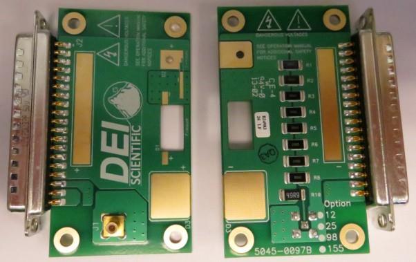
The on-board current monitor on the Laser Output PCBA provides a real-time view of the diode current. The monitor (J1) has a ratio of 125 mV/A into a 50 ohm termination, which connects straight to an oscilloscope through the supplied current/voltage monitor cable.
8Applications
The PCX-7401 suits applications that need precise, repeatable current pulses into a single diode or a small array, with bias control to set the operating point.
- Diode lasers, bars, and arrays. Drive single emitters and small arrays with clean current pulses and an independent bias channel to hold the device near threshold.
- LiDAR and rangefinding. Generate short, repeatable current pulses for time-of-flight measurement with low cycle-to-cycle jitter.
- Optical test and characterization. Map L-I curves, slope efficiency, and threshold with fine 1 mA current steps and bias control.
- Pulsed photonics and sensing. Produce continuous duty-cycle trains or single shots, internally or externally triggered, for laboratory experiments.
9Ordering Information
| Part number | Description |
|---|---|
| PCX-7401 | Precision Pulsed Current Source |
| 6045-0003 | Output Stripline Cable |
| 6045-0097 | Laser Output PCBA |
| PCA-9550 | Current/Voltage Monitor Cable |
| PCA-9410 | BNC Shorting Connector |
Each PCX-7401 is delivered with an output stripline cable, laser output PCBA, current/voltage monitor cable, and BNC shorting connector.
Contact
For a quote, configuration help, or application support, reach the Berkeley Nucleonics team.
Email: info@berkeleynucleonics.com
Phone: 800-234-7858