Purpose
This application note describes how the Berkeley Nucleonics signal generators can be used as external sources for Anritsu's VectorStar™ VNA product line.
Introduction
Anritsu VectorStar™ VNAs use a dedicated GPIB (general purpose interface bus) port to communicate with up to four external sources. External sources are required to measure multi-port DUTs like mixers.
Berkeley Nucleonics signal generators with option GPIB support all GPIB features, commands and queries required by the VectorStar™ system. That enables using them as external sources.
Prerequisites
Any Berkeley Nucleonics signal generator fulfilling the following requirements can be used as an external source for VectorStar™ VNAs:
- Option GPIB
- Firmware 0.4.123 or later
Connections
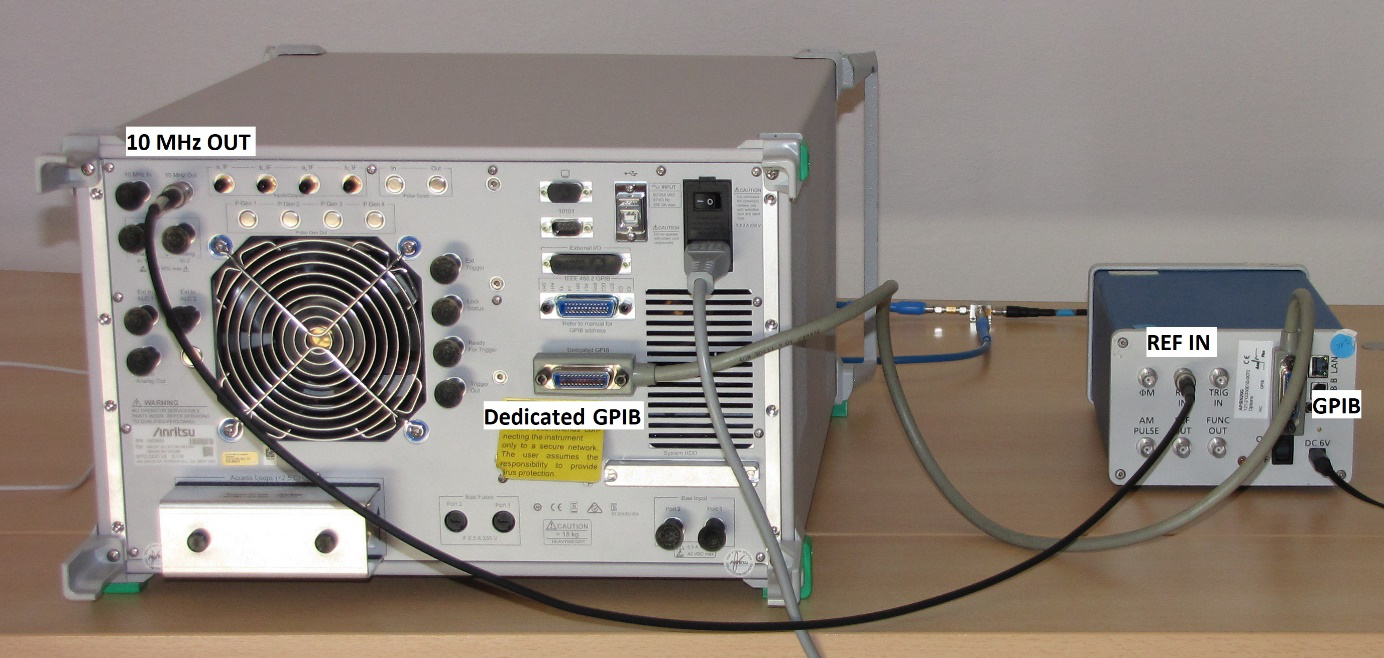
External sources can be connected to the VNA dedicated GPIB port.
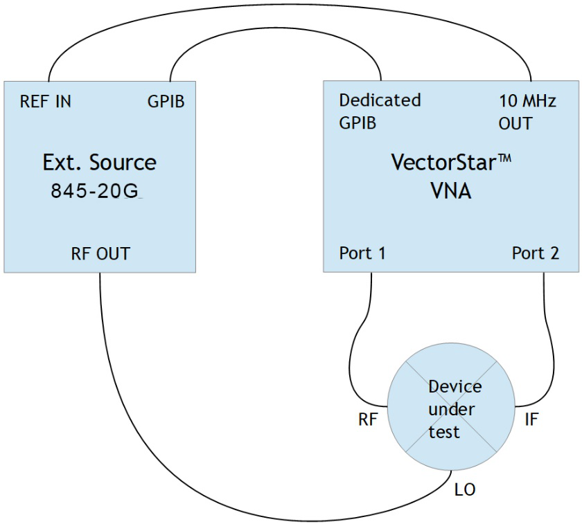
For time base synchronization use a BNC cable to connect VNA reference output "10 MHz OUT" and signal generator reference input "REF IN" as shown in figure 1.
Signal generator setup
Some configuration must be done before the signal generator can be used as an external source:
- The VectorStar™ system expects external sources to listen to specific GPIB addresses. The default setting is:
- external source 1 at GPIB address 4
- external source 2 at GPIB address 5
- external source 3 at GPIB address 2
- external source 4 at GPIB address 3
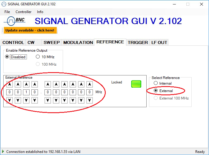
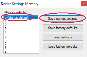
- It is recommended that all external sources are locked to the reference of the VectorStar™ system. Use the Berkeley Nucleonics GUI to configure the generator for 10 MHz external reference as shown in figure 4. This configuration can be stored as the power up default. See figure 5.
VNA setup
Anritsu VectorStar™ VNAs detect connected external sources automatically. Proper detection can be verified under
Application → Rcvr Config → Multiple Source → Ext. Src Control
where a
State[Active/Inactive]
button shows up for each detected source. Then turn the external source to active state to use it.
If an external source is not detected, check the GPIB cable, check the sources GPIB address configuration or power cycle it.
An example: mixer downconversion loss characterization
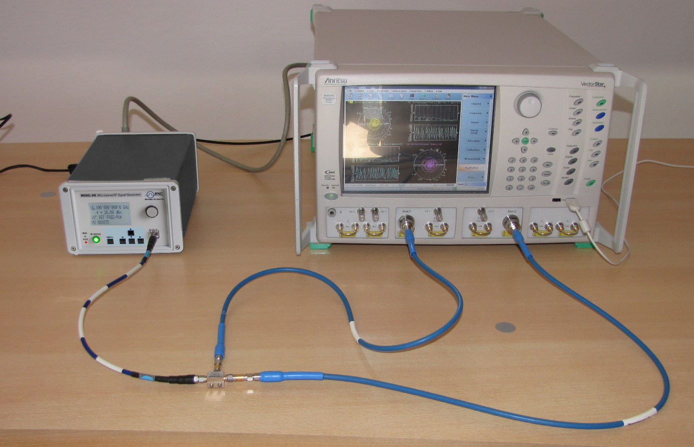
This example starts with the setup shown in figures 2 and 6. A mixer is connected to the VNA and an external source: Mixer RF connected to VNA port 1, IF to VNA port 2, LO to the external source.
Mixer downconversion loss shall be measured at
- a fixed IF of 30 MHz
- an RF range of 1…18 GHz
- a fixed RF input power level of -10 dBm
- a fixed LO level of +7 dBm
An 845-20G is used as an external source generating the 0.97…17.97 GHz swept LO signal.
The setup steps are:
- Configure the Model 845-20G as explained under "Signal Generator Setup".
- Verify the VNA detects it as explained under "VNA Setup".
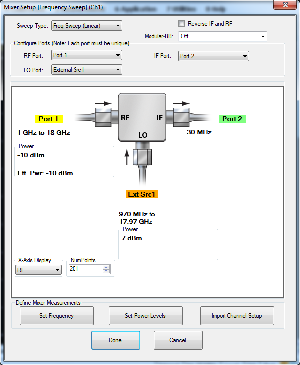
- Open the mixer measurement configuration dialog (figure 7). On the VNA:
Application → Mixer → Mixer Setup (Active Channel)
The dialog opening lets the user enter the setup.
- Check the port assignments: Mixer RF connects to VNA port 1, IF to port 2 and LO to external source 1.
- Configure frequencies and frequency ranges:
- RF frequency mode "swept", range 1…18 GHz
- LO frequency mode "auto"
- IF frequency mode "fixed", at 30 MHz
- Define power levels:
- RF power -10 dBm
- LO power +7 dBm
When done, the VNA will configure the external source automatically.
- The receiver port can now be calibrated. In this example we skip driver power calibration. Instead a minimal trough line calibration is performed.
- Replace the mixer RF-IF path with a through line.
- Run the through line calibration:
Calibration → Calibrate → Manual Cal. → RcvrCal./Normalization → Thru → 1-2
- Connect the mixer again.
In addition, power and match calibration shall be performed to get accurate results. Refer to the VectorStar Calibration and Measurement Guide [2] for details.
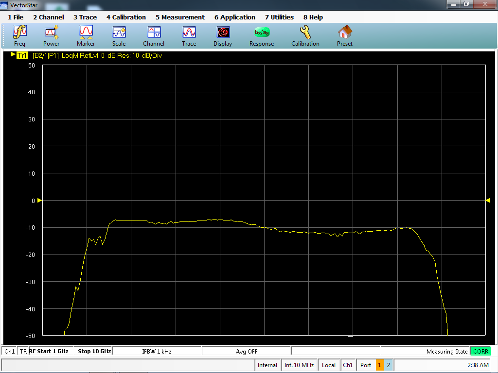
- Classical S-parameters are not useful in setups with different port frequencies. Instead the trace displayed can be configured to show scalar measurements. In typical mixer measurements the scalar B2/1 (port 2 received power) response is relevant.
The active trace can be configured under:
Response → User defined
then select
- Numerator: B2
- Denominator: 1
- Driver port: Port 1
The resulting plot (figure 8) shows scalar mixer downconversion loss.
Related documents
- [1] Operation Manual, VectorStar™ MS464xB Series Microwave Vector Network Analyzer, PN: 10410-00317, Revision P, 2018, Anritsu Company. https://dl.cdn-anritsu.com/en-us/test-measurement/files/Manuals/Operation-Manual/10410-00317P.pdf
- [2] Calibration and Measurement Guide, VectorStar™ MS464xB Series Microwave Vector Network Analyzer, Revision R, PN: 10410-00318, 2018, Anritsu Company. https://dl.cdn-anritsu.com/en-us/test-measurement/files/Manuals/Measurement-Guide/10410-00318R.pdf