Introduction
For fast, time-critical settings like frequency changes, the device can be controlled over the Fast Control Port (FCP). It is a parallel port that can be operated in either '8-bit Mode' or '16-bit Mode'. If activated, the device's frequency and/or amplitude are controlled by the FCP. With FCP, memory is addressed and filled with frequency or amplitude information.
To enable and configure the communication over FCP, the device must be configured in advance over SCPI.
Configuring the FCP
To select the operating mode of the Fast Control Port, the FCP must be configured with an SCPI command:
[:SOURce]:FCPort:MODE 8|8B|8Bits|16|16B|16BitsConfigures the operation mode of the FCP.
*RST value: 16
Further related commands are documented in the Programmer's Manual [1].
8-bit Mode
'8-bit Mode' is limited to frequency control of one RF channel or to a common frequency on several channels. The frequency can either be selected by the index of a pre-defined frequency list or by sending the complete frequency word. On multi-channel devices, it is not possible to operate one channel with a list of frequencies and the other with a frequency word.
Setting the RF frequency and amplitude
The RF output signal can be configured via the FCP with
- The frequency word (FW). It is 48 bits wide, unsigned, and is calculated as
FW = Frequency in Hz * 256. - The amplitude word (AW). It is 16 bits wide, signed (two's complement), and is calculated as
AW = Amplitude in dBm * 127.
8-bit mode is limited to only one set of one frequency and one amplitude word. All channels with FCP enabled will use the same set.
However, frequency vs. amplitude words may be used individually: one channel (e.g., 3) can be under FCP amplitude control, while another channel (e.g., 2) is under FCP frequency control.
The signal generator must be set up to be controlled by FCP with SCPI commands:
[:SOURce#]:FCPort:CONTrol:FREQuency ON|OFF|1|0Enables or disables FCP frequency control on the specified RF channel
*RST value: OFF
[:SOURce#]:FCPort:CONTrol:AMPLitude ON|OFF|1|0Enables or disables FCP amplitude control on the specified RF channel
*RST value: OFF
Complete SCPI command sequence for frequency mode:
| Command | Description |
|---|---|
SOUR<x> | Select the RF output |
OUTP ON | Enables RF output |
FREQ <x> | Sets initial RF output frequency |
POW <x> | Sets RF output power |
FCP:MODE 8 | Sets FCP to 8-bit Mode |
FCP:CONT:FREQ ON | Enables FCP frequency control |
For amplitude mode, modify the last command:
| Command | Description |
|---|---|
FCP:CONT:AMPL ON | Enables FCP amplitude control |
Both modes can be combined to full frequency and amplitude control:
| Command | Description |
|---|---|
FCP:CONT:FREQ ON;AMPL ON | Enables combined FCP frequency and amplitude control |
The Frequency Word (FW) is written sequentially to address 0 to 11. Writing bit 47 (MSB) of the FW triggers the processing and updates of the RF output signal that is RF Frequency = FW value * 1 Hz / 256.
The Amplitude Word (AW) is written sequentially to address 12 to 15. Writing bit 15 (MSB) of the AW triggers the processing and updates of the RF output signal that is RF Amplitude = AW value * 1 dBm / 128.
In combined frequency and amplitude mode, writing the MSB of both words (global bit 63 = AW bit 15) triggers the update. This ensures simultaneous frequency and amplitude update at the RF output.
| Address | Data |
|---|---|
| 0 | FW (frequency word) bits [3...0] |
| 1 | FW (frequency word) bits [7...4] |
| 2 | FW (frequency word) bits [11...8] |
| 3 | FW (frequency word) bits [15...12] |
| 4 | FW (frequency word) bits [19...16] |
| 5 | FW (frequency word) bits [23...20] |
| 6 | FW (frequency word) bits [27...24] |
| 7 | FW (frequency word) bits [31...28] |
| 8 | FW (frequency word) bits [35...32] |
| 9 | FW (frequency word) bits [39...36] |
| 10 | FW (frequency word) bits [43...40] |
| 11 | FW (frequency word) bits [47...44] |
| 12 | AW (amplitude word) bits [3...0] |
| 13 | AW (amplitude word) bits [7...4] |
| 14 | AW (amplitude word) bits [11...8] |
| 15 | AW (amplitude word) bits [15...12] |
Timing
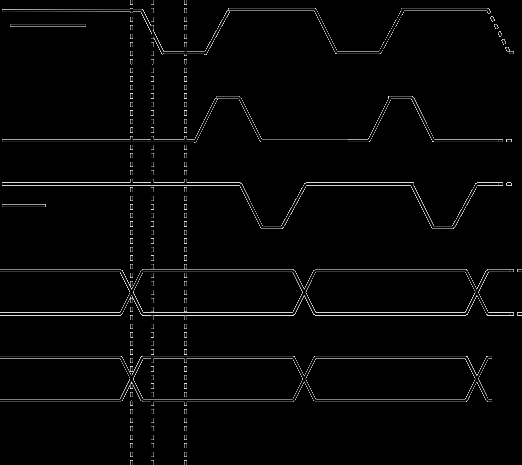
Address and data are transferred at the same time. The signal generator reads the data upon a falling edge on the strobe line. The signal generator confirms the received data with ACK and informs the controller by the BUSY signal while processing the information.
Signals: Address A<3..0>, Data D<3..0>, STROBE, ACK, BUSY
| Parameter | Value |
|---|---|
| Setup-time t1 | > -10 ns |
| Hold-time t2 | > 60 ns |
SCPI & FCP Example
This is an SCPI example to set the RF output frequency of RF output 2 on a multi-channel system:
| Command | Description |
|---|---|
*RST | Reset device |
OUTP2 ON | Enables RF output 2 |
POW 5 | Sets RF output power to 5 dBm |
FCP:MODE 8 | set FCP to 8-bit Mode |
SOUR2:FCP:CONT:FREQ ON | Enables FCP on RF output 2 |
*OPC? | Check if the operation is complete |
After successfully configuring RF channel 2, writing FW 256'000'000'000 to the FCP leads to a 1 GHz RF signal.
FCP:CONT:FREQ ON must be enabled on each channel to provide the same frequency on multiple channels.
Selecting pre-defined RF Frequency
The device plays points from a pre-defined list of frequency settings with max 20'000 entries in this mode. It is similar to a list sweep but with the FCP selecting the pre-defined frequency.
8-bit mode is limited to only one list word. All channels with FCP enabled will use the same list word.
However, the frequency list of each channel can be configured individually: e.g., point 1 can be 1 GHz for channel 1 but 2 GHz for channel 2.
The signal generator must be setup to be controlled by FCP with an SCPI command:
[:SOURce]:FCPort:CONTrol:LIST ON|OFF|1|0Enables or disables FCP on the specified RF channel
*RST value: OFF
Complete SCPI command sequence to set up RF output to play selected frequency point:
| Command | Description |
|---|---|
SOUR <channel> | Select the RF output |
OUTP ON | Enables RF output |
POW <x> | Sets RF output power |
LIST:FREQ <f1>,<f2>,<f3>,...,<fn> | Defines a list of frequency settings |
FCP:MODE 8 | Sets FCP to 8-bit Mode |
FCP:CONT:LIST ON | Enables FCP control |
To select a pre-defined frequency, a 16-bit data list word (LW) must be written to address 0 to 3. Writing bit 15 (MSB) triggers the processing and update of the RF output signal. Writing 1 to the list word (LW) plays <f1>, LW = 2 plays <f2> etc.
| Address | Data |
|---|---|
| 0 | LW (list word) bits [3...0] |
| 1 | LW (list word) bits [7...4] |
| 2 | LW (list word) bits [11...8] |
| 3 | LW (list word) bits [15...12] |
Timing
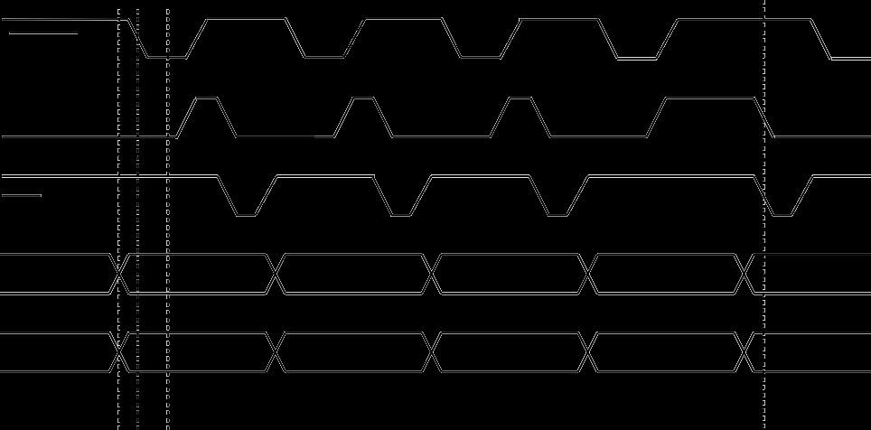
Address and data are transferred at the same time. The signal generator reads the data upon a falling edge on the strobe line. The signal generator confirms the received data with ACK and informs the controller by the BUSY signal while processing the information.
Signals: Address A<3..0>, Data D<3..0>, STROBE, ACK, BUSY
| Parameter | Value |
|---|---|
| Setup-time t1 | > -10 ns |
| Hold-time t2 | > 60 ns |
SCPI & FCP Example
This is an SCPI example to set up RF output 1 and RF output 3 on a multi-channel system to play selected frequency point:
| Command | Description |
|---|---|
*RST | Resets device |
OUTP1 ON | Enables RF output 1 |
OUTP3 ON | Enables RF output 3 |
POW1 5 | Sets RF output power to 5 dBm |
POW3 7 | Sets RF output power to 7 dBm |
SOUR1:LIST:FREQ 1 GHz,1.5 GHz,2 GHz | Defines a list of frequencies |
SOUR3:LIST:FREQ 1.2 GHz,1.25 GHz,1.3 GHz | Defines a list of frequencies |
FCP:MODE 8 | Sets FCP to 8-bit Mode |
SOUR1:FCP:CONT:LIST ON | Enables FCP on RF output 1 |
SOUR3:FCP:CONT:LIST ON | Enables FCP on RF output 3 |
*OPC? | Checks if the operation is complete |
After successfully configuring RF output 1 and 3, writing 1 to the list word (LW) over the FCP, would simultaneously play
- 1 GHz on RF output 1 with an output power of 5 dBm
- 1.2 GHz on RF output 3 with an output power of 7 dBm
16-bit Mode
The '16-bit Mode' extends the '8-bit Mode' with multi-channel support. The frequency can either be selected by the index of a pre-defined frequency list or by sending the complete frequency word. On a multi-channel system, it is possible to operate each channel individually with a frequency list, the frequency, or the amplitude word.
Setting the RF Frequency and Amplitude
The RF output signal can be configured via the FCP with
- The frequency word (FW). It is 48 bits wide, unsigned, and is calculated as
FW = Frequency in Hz * 256. - The amplitude word (AW). It is 16 bits wide, signed (two's complement), and is calculated as
AW = Amplitude in dBm * 127.
The signal generator must be set up to be controlled by FCP with SCPI commands:
[:SOURce]:FCPort:CONTrol:FREQuency ON|OFF|1|0Enables or disables FCP to set frequency word on the specified RF channel
*RST value: OFF
[:SOURce#]:FCPort:CONTrol:AMPLitude ON|OFF|1|0Enables or disables FCP amplitude control on the specified RF channel
*RST value: OFF
Complete SCPI command sequence for frequency mode:
| Command | Description |
|---|---|
SOUR<x> | Select the RF output |
OUTP ON | Enables RF output |
FREQ <x> | Sets initial RF output frequency |
POW <x> | Sets RF output power |
FCP:MODE 16 | Sets FCP to 16-bit Mode |
FCP:CONT:FREQ ON | Enables FCP control |
For amplitude mode, modify the last command:
| Command | Description |
|---|---|
FCP:CONT:AMPL ON | Enables FCP amplitude control |
Both modes can be combined to full frequency and amplitude control:
| Command | Description |
|---|---|
FCP:CONT:FREQ ON;AMPL ON | Enables combined FCP frequency and amplitude control |
The Frequency Word (FW) is written sequentially to address 0 to 5. Writing bit 47 (MSB) of the FW triggers the processing and updates of the RF output signal that is RF Frequency = FW value * 1 Hz / 256.
The Amplitude Word (AW) is written sequentially to address 6 to 7. Writing bit 15 (MSB) of the AW triggers the processing and updates of the RF output signal that is RF Amplitude = AW value * 1 dBm / 128.
In combined frequency and amplitude mode, writing the MSB of both words (global bit 63 = AW bit 15) triggers the update. This ensures simultaneous frequency and amplitude update at the RF output.
| RF Channel | Address | Data |
|---|---|---|
| 1 | 0 | FW (frequency word) bits [7...0] |
| 1 | 1 | FW (frequency word) bits [15...8] |
| 1 | 2 | FW (frequency word) bits [23...16] |
| 1 | 3 | FW (frequency word) bits [31...24] |
| 1 | 4 | FW (frequency word) bits [39...32] |
| 1 | 5 | FW (frequency word) bits [47...40] |
| 1 | 6 | AW (amplitude word) bits [7...0] |
| 1 | 7 | AW (amplitude word) bits [15...8] |
| 2 | 16...21 | FW (frequency word) |
| 2 | 22...23 | AW (amplitude word) |
| 3 | 32...37 | FW (frequency word) |
| 3 | 38...39 | AW (Amplitude word) |
| 4 | 48...53 | FW (frequency word) |
| 4 | 54...55 | AW (amplitude word) |
Timing
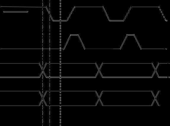
Address and data are transferred at the same time. The signal generator reads the data upon a falling edge on the strobe line. The signal generator confirms the received data with ACK and informs the controller by the BUSY signal while processing the information.
Signals: Address A<7..0>, Data D<7..0>, STROBE, BUSY
| Parameter | Value |
|---|---|
| Setup-time t1 | > -10 ns |
| Hold-time t2 | > 60 ns |
SCPI & FCP example
This is an SCPI example to set the RF output frequency of RF output 2 on a multi-channel system:
| Command | Description |
|---|---|
*RST | Reset device |
OUTP1 ON | Enables RF output 1 |
OUTP3 ON | Enables RF output 3 |
POW1 5 | Sets RF output power to 5 dBm |
POW3 7 | Sets RF output power to 7 dBm |
FCP:MODE 16 | Sets FCP to 16-bit Mode |
SOUR1:FCP:CONT:FREQ ON | Enables FCP on RF output 1 |
SOUR3:FCP:CONT:FREQ ON | Enables FCP on RF output 3 |
*OPC? | Check if the operation is complete |
After successfully configuring RF channels 1 and 3, writing FW 256'000'000'000 to the FCP would simultaneously play
- 1 GHz on RF output 1 with an output power of 5 dBm
- 1 GHz on RF output 3 with an output power of 7 dBm
With FW revision > 0.152, for each RF channel, an individual frequency, and amplitude word can be set.
Selecting pre-defined RF Frequency
The device plays points from a pre-defined list of frequency settings with max 20'000 entries in this mode. It is similar to a list sweep but with the FCP selecting the pre-defined frequency.
The signal generator must be set up to be controlled by FCP with an SCPI command:
[:SOURce]:FCPort:CONTrol:LIST ON|OFF|1|0Enables or disables FCP on the specified RF channel
Complete SCPI command sequence to set up RF output to play selected frequency point:
| Command | Description |
|---|---|
SOUR <channel> | Select the RF output |
OUTP ON | Enables RF output |
POW <x> | Sets RF output power |
LIST:FREQ <f1>,<f2>,<f3>,...,<fn> | Defines a list of frequency settings |
FCP:MODE 16 | Sets FCP to 16-bit Mode |
FCP:CONT:LIST ON | Enables FCP control |
For each RF channel, a 16-bit data list word (LW) must be written to address 0 to 1 to select the pre-defined frequencies (see table below). Writing bit 15 (MSB) of a list word 1 triggers the processing and update of the corresponding channel's RF output signal. Writing 1 to the list word (LW) plays <f1>, LW = 2 plays <f2> etc.
| RF channel | Address | Data |
|---|---|---|
| 1 | 0 | LW (list word) bits [7...0] |
| 1 | 1 | LW (list word) bits [15...8] |
| 2 | 16 | LW (list word) bits [7...0] |
| 2 | 17 | LW (list word) bits [15...8] |
| 3 | 32 | LW (list word) bits [7...0] |
| 3 | 33 | LW (list word) bits [15...8] |
| 4 | 48 | LW (list word) bits [7...0] |
| 4 | 49 | LW (list word) bits [15...8] |
Timing
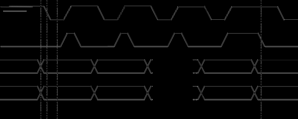
Address and data are transferred at the same time. The signal generator reads the data upon a falling edge on the strobe line. The signal generator informs the controller by the BUSY signal while processing the information.
Signals: Address A<7..0>, Data D<7..0>, STROBE, BUSY
| Parameter | Value |
|---|---|
| Setup-time t1 | > -10 ns |
| Hold-time t2 | > 60 ns |
SCPI & FCP Example
This is an SCPI example to set up RF output 1 and RF output 3 on a multi-channel system to play selected frequency point:
| Command | Description |
|---|---|
*RST | Reset device |
OUTP1 ON | Enables RF output 1 |
OUTP3 ON | Enables RF output 3 |
POW1 5 | Sets RF output power to 5 dBm |
POW3 7 | Sets RF output power to 7 dBm |
SOUR1:LIST:FREQ 1 GHz,1.5 GHz,2 GHz | Defines a list of frequencies |
SOUR3:LIST:FREQ 1.2 GHz,1.25 GHz,1.3 GHz | Defines a list of frequencies |
FCP:MODE 16 | Sets FCP to 16-bit Mode |
SOUR1:FCP:CONT:LIST ON | Enables FCP on RF output 1 |
SOUR3:FCP:CONT:LIST ON | Enables FCP on RF output 3 |
*OPC? | Check if the operation is complete |
After successfully configuring RF output 1 and 3, writing 1 to the list word (LW) over the FCP, would simultaneously play
- 1 GHz on RF output 1 with an output power of 5 dBm
- 1.2 GHz on RF output 3 with an output power of 7 dBm
With FW revision > 0.152, for each RF channel, an individual list word can be set.
Electrical Specification
| Parameter | Value |
|---|---|
| Input signal | 0 V to 5 V |
| Input impedance | 4,7 kΩ |
| Maximum toggle rate | 10 MHz |
RFU = Reserved for Future Use. Ports should not be connected.
| Pin | Signal (8-bit Mode) | Signal (16-bit Mode) | Pin | Signal (8-bit Mode) | Signal (16-bit Mode) |
|---|---|---|---|---|---|
| 1 | STROBE (in) | STROBE (in) | 14 | RFU | Data 3 |
| 2 | Address 0 | Address 0 | 15 | RFU | Data 4 |
| 3 | Address 1 | Address 1 | 16 | RFU | Data 5 |
| 4 | Address 2 | Address 2 | 17 | RFU | Data 6 |
| 5 | Address 3 | Address 3 | 18 | RFU | Data 7 |
| 6 | Data 0 | Address 4 | 19 | GND | GND |
| 7 | Data 1 | Address 5 | 20 | GND | GND |
| 8 | Data 2 | Address 6 | 21 | GND | GND |
| 9 | Data 3 | Address 7 | 22 | RFU | RFU |
| 10 | ACK (out) | Data 0 | 23 | GND | GND |
| 11 | BUSY (out) | BUSY (out) | 24 | RFU | RFU |
| 12 | RFU | Data 1 | 25 | GND | GND |
| 13 | RFU | Data 2 | 26 | GND | GND |
Cable Assembly
For the external wiring of the FCP port, a cable with 26 conductors and MDR-connector is available.
To build a custom cable, the individual components are listed below:
| Description | Manufacturer | Part Number |
|---|---|---|
| Connector Plug MDR 26 Pin | 3M | 10126-3000PE |
| Connector Backshell MDR 26 Pin | 3M | 10326-3210-006 |
| Cable shielded 26 wire 28 AWG | 3M | 3600B/26 |
The table below lists the mapping of connector pin and wire colors.
| Pin | Wire Color (Solid) | Wire Color (Band) | Comments |
|---|---|---|---|
| 1 | Black | Red | twisted with Pin 20 |
| 2 | Black | White | |
| 3 | White | Black | |
| 4 | Blue | Red | |
| 5 | Red | Blue | |
| 6 | Red | White | |
| 7 | White | Red | |
| 8 | Red | Brown | |
| 9 | Brown | Red | |
| 10 | Blue | Black | |
| 11 | Black | Blue | |
| 12 | Brown | Black | |
| 13 | Black | Brown | |
| 14 | Orange | Red | |
| 15 | Red | Orange | |
| 16 | Red | Yellow | |
| 17 | Yellow | Red | |
| 18 | Black | Yellow | |
| 19 | Yellow | Black | |
| 20 | Red | Black | twisted with Pin 1 |
| 21 | Orange | Black | |
| 22 | Black | Orange | |
| 23 | Green | Black | |
| 24 | Black | Green | |
| 25 | Green | Red | |
| 26 | Red | Green |
Further Documentation
[1] BNC Programmer's Manual for Signal Generators