What is particle image velocimetry?
Particle image velocimetry [PIV] is a noninvasive technique for measuring flow velocities. Unlike point measurement tools like anemometers, laser doppler velocimeters, and pitot-static tubes, PIV allows velocity measurements over an entire two-dimensional plane simultaneously without disturbing the flow being studied. Since it was developed over a quarter century ago, this technique has become a staple of fluid dynamics research in aerodynamics, biofluidics, combustion, microfluidics, and environmental fluids. In both academia and commerce, PIV is the perfect tool for exploring flow velocities in research and development applications.
How does particle image velocimetry work?
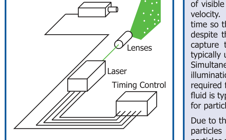
Instead of using an invasive probe, PIV relies on sequential images of visible features within the flow to statistically determine the local velocity. These images must be separated by a short amount of time so that the same visible features in each image are identifiable despite the displacement or deformation imposed by the fluid. To capture these images, a dual-pulsed Nd:YAg or Nd:YLF laser is typically used to illuminate the flow with two brief pulses [Figure 1]. Simultaneously, a high-speed CCD or CMOS camera captures the two illumination pulses in sequential image frames. Since optical access is required for both laser illumination and camera capture, the working fluid is typically translucent and lacks the identifiable features needed for particle image velocimetry.
Due to the lack of inherent tracers, fluid flows are often seeded with particles that follow but do not alter the fluid motion. Spherical particles are often used due to their well understood fluid interactions and visual response to illumination. To enhance their contrast with any fluid or background contaminates, the particles are usually coated to reflect, refract, or fluoresce incident laser light. As the laser fires, the particles in the region of interest are illuminated and produce a tracer field for image capture. For optimal PIV results, the captured images should reveal sharp, point-like particles without any streaking or blurring.
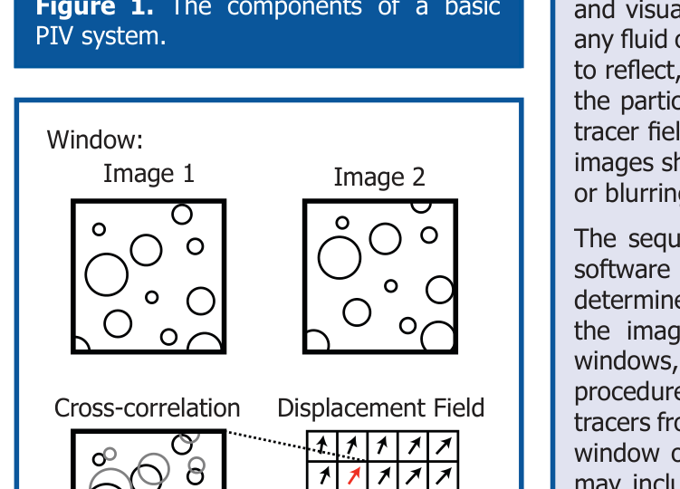
The sequential images of these tracer fields are processed by PIV software to extract the velocity of the fluid flow. To statistically determine the displacement of individual groups of tracer particles, the images are subdivided into smaller pixel groups, known as windows, which are cross-correlated [Figure 2]. This statistical procedure identifies the most probable displacement of the flow tracers from one laser pulse to the next using the pixel pattern of each window on pairs of images. More advanced processing algorithms may include window displacement and deformation to improve the cross-correlation. Once the most probable displacement is known for each window, the velocity field can be calculated using the known separation time between images. Once the velocity field is known, further post-processing may be used to filter the results and produce publication-quality graphics, including velocity vector, vorticity, and streamline plots.
How does timing affect particle image velocimetry?
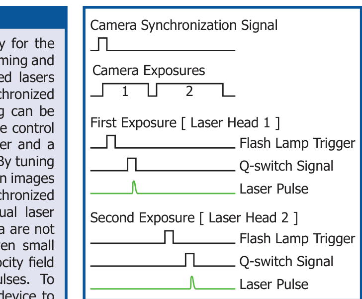
Since repeatable and accurate timing signals are necessary for the collection of reliable particle image velocimetry results, the timing and synchronization requirements can be complex. Dual-pulsed lasers can require up to four signals each to control the pair of synchronized pulses necessary for PIV [Figure 3]. While internal timing can be used to reduce the number of signals required, for complete control of each laser head, a flash lamp trigger to charge the laser and a Q-switch signal to trigger laser pulse emission are needed. By tuning these four separate signals, both the time separation between images and the relative beam intensity are adjustable. A fifth synchronized signal coordinates the camera exposure with the individual laser pulses. If the timing signals activating the laser and camera are not synchronized, the velocity field may be irrecoverable. Even small errors in the timing will lead to errors in the measured velocity field due to its direct reliance on the time separation between pulses. To maximize the ease of setup and reliability, using a single device to manage the timing pulses required can ensure precise and accurate particle image velocimetry results.
How can BNC meet your timing needs?
While the complexities of timing and synchronization necessary for PIV can be overwhelming, Berkeley Nucleonics Corporation [BNC] offers multiple products to manage your PIV timing needs with a single device. The BNC Model 575 Digital Delay/Pulse Generator and Model 725 Multi-Trigger Digital Delay Generator offer simple yet accurate timing and synchronization solutions for particle image velocimetry.
The BNC Model 575 is designed to handle the precise timing needs of high-speed PIV while offering an intuitive onboard interface [Figure 4]. With up to 8 channels and a 250 picosecond resolution, the Model 575 is capable of controlling laser and camera timing in addition to other experimental equipment requiring timing or synchronization. The onboard programming interface bypasses the need for devoting computer resources to timing and synchronization while maintaining adaptability. The Model 575 is an excellent choice to efficiently acquire data with a basic PIV system while maintaining a short learning curve.
The BNC Model 725 works equally well for PIV experiments but offers extensive control for more experienced users [Figure 5]. Unlike the Model 575 which uses a common clock to trigger up to 8 channels, the Model 725 offers independent triggering of up to 8 channels with a resolution of 10 nanoseconds. While the Model 725 functions as a stand-alone generator, full user control is available with the included timerPRO computer software. Drivers are also included for integration into LabVIEW™. Once programmed, the Model 725 allows repeatable, precise, and accurate control of your PIV experiment.
Both the BNC Model 575 and 725 can save time and money when setting up and operating any PIV system.
![Figure 4. BNC Model 575 Digital Delay/Pulse Generator. 250ps delay and width resolution per channel; 50ps channel jitter / 800ps RMS external jitter; independent clock rates for each channel; dual inputs [Gate + Trig / 2 Trig]; programmable [Ethernet / USB / RS-232 / GPIB].](../figures/appnotes/575-piv/fig-004.png)
![Figure 5. BNC Model 725 Multi-Trigger Delay Generator. Trigger-pulse delay: 50ns - 1370s; inputs: 8 external and 7 internal; outputs: 8 internal [to timing processors]; delay jitter from internal source: 200ps; external trigger duration: 50ns.](../figures/appnotes/575-piv/fig-005.png)